printable version printable version
Removal and installation of headlights
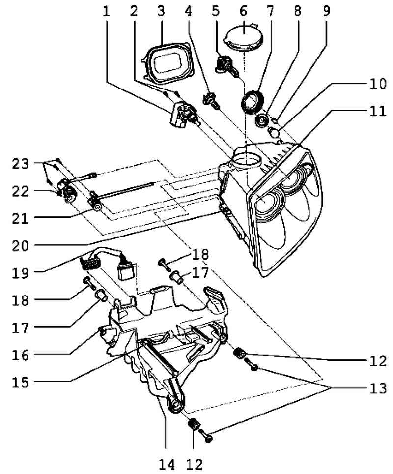
| Fig. 7.88. The components of the front lights: 1 - left-leveling actuator or actuator right-leveling; 2 - fixing bolts; 3 - cover; 4 - left low beam lamp or right low beam lamp; 5 - left lamp beam or right light beam; 6 - cap; 7 - cap; 8 - lamp socket with a handle; 9 - left parking light bulb or right parking light bulb; 10 - the left front turn signal lamp or the right front turn signal lamps; 11 - lamp; 12 - the adjusting plug; 13 - fixing screws; 14 - fixing lights; 15 - fixing loop; 16 - the locking bolt; 17 - mounting sleeve; 18 - fixing screws; 19 - pin connector; 20 - lock bracket; 21 - adjusting the rotation of the drive shaft beam; 22 - drive shaft adjustment and dipped beam adjustment; 23 - fixing bolts
|
NOTE Check the factors that influence the control of lights, if necessary - to adjust the headlights. |
NOTE Disconnect the mass of the battery is not necessary. |
The illustrations show removal and installation of the left headlight.
Withdrawal Turn the ignition and all electrical consumers and remove ignition key. Click on the spotlight.
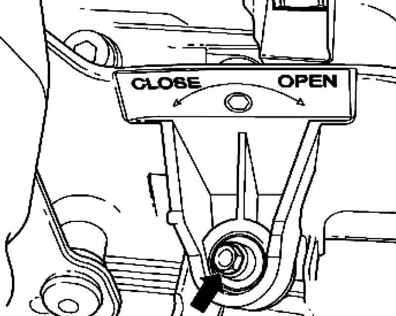
Turn the locking bolt in the direction of the arrow Open (sticker) until resistance is felt (fig. 7.89).
NOTE Turn the bolt without using force, otherwise there is a risk to break the lock mechanism. Farah is pushed forward. |
Pull the headlight of a niche in the wing until you feel stress.
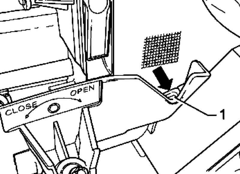
Hold the retaining clip 1 down, remove the spotlight from the recess of the body (Fig. 7.90).
Setting Install the headlamp guides.
NOTE The guide should not be contamination. |
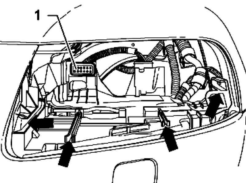
Check the plug is firmly fixed in the fixture lamps 1, before inserting the spotlight in the guides (Fig. 7.91).
Gently push the spotlight in the recess of the body.
NOTE You should hear a "clear" click. This means that the retaining bracket is fixed. |
Turn the locking bolt in the direction of the arrow Close (sticker) until resistance is felt (fig. 7.89). Gently push the spotlight and turn the screw further in the direction of arrow Close (sticker). The fixing bracket should snap into place with a clearly audible click. Check the lights on the same side clearances. If the gaps between the headlamp body and uneven, it is necessary to adjust the position of the lights. Check the operation of lights, including all of its functions. Check the setting of the headlights, if necessary - adjust.
|