printable version printable version
Removing and installing starter, 10-cyl. TDI 4,9 liter engine, automatic transmission
Withdrawal Remove the engine. Remove the right turbocharger.
Click the button and remove the insulation of the magnetic switch (Fig. 7.40).
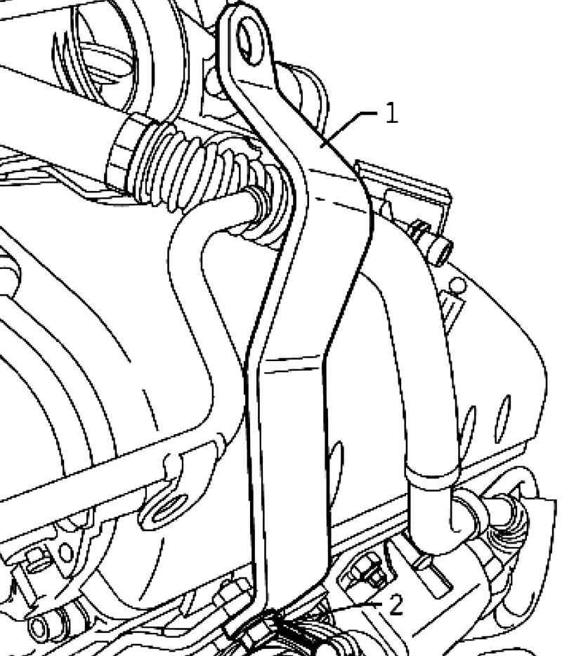
| Fig. 7.42. Eyebolts at the back of the right cylinder head
|
Screw the eyebolts T10126 1 with a bolt M8h40 2 at the back of the right cylinder head (Fig. 7.42).
ATTENTION Ship conveyor plate should hit when screwing in the hole of the holder fixed to the engine. |
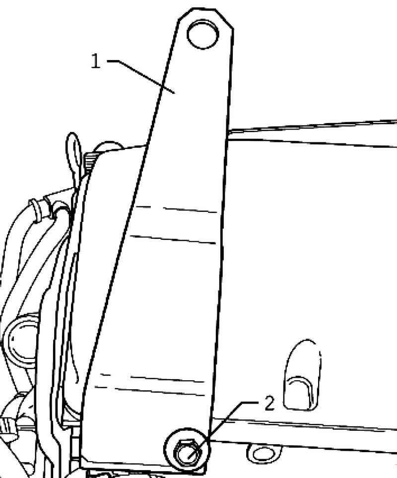
| Fig. 7.43. Eyebolts at the front of the left cylinder head
|
Screw the eyebolts T10126 / January 1 with a bolt M8h40 2 front to the left cylinder head (Fig. 7.43).
ATTENTION Ship conveyor plate should hit when screwing in the hole of the holder fixed to the engine. |
Hang the device for hanging crane VAS 3033 to 6100. Hang eyebolts T10126 and T10126 / 1 to a device for hanging 3033. Lift drive with a crane VAS 6100.
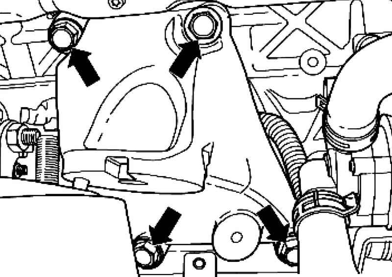
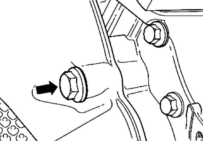
Remove the 4 mounting bolts M10h95 right engine mount and remove the right support (Fig. 7.44).
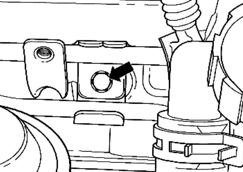
| Fig. 7.45. Fixing screw tube cooling system for engine block
|
Remove the retaining bolt tube cooling system for the engine block (Fig. 7.45).
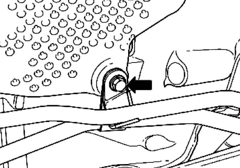
| Fig. 7.46. Fixing screw tube cooling system for gearbox
|
Remove the retaining bolt tube cooling system on the gearbox (Fig. 7.46).
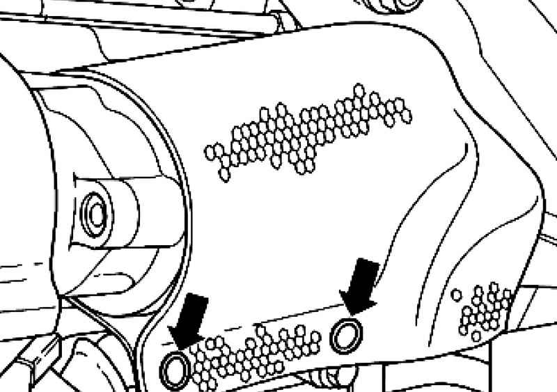
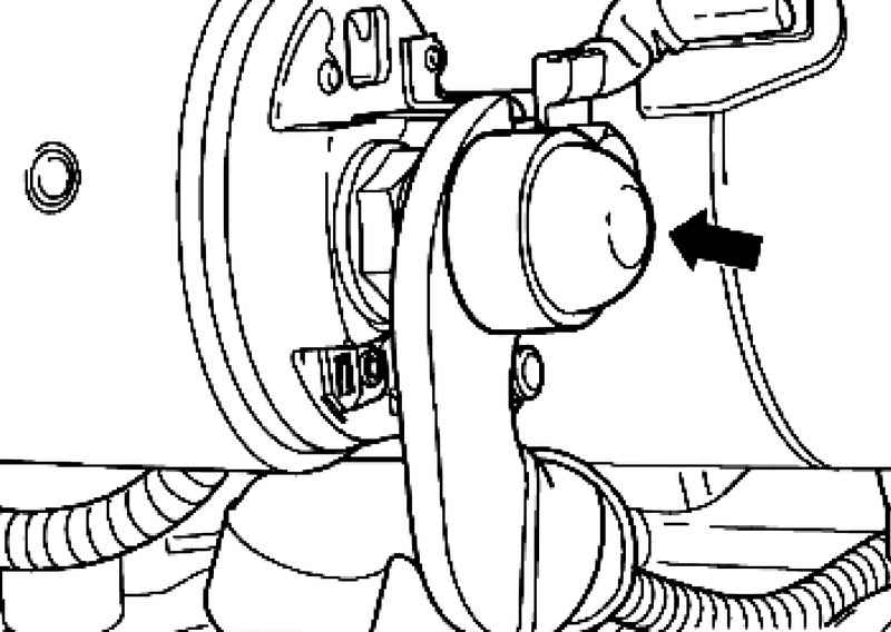
Remove the protective cap with electromagnetic starter switch (Fig. 7.47).
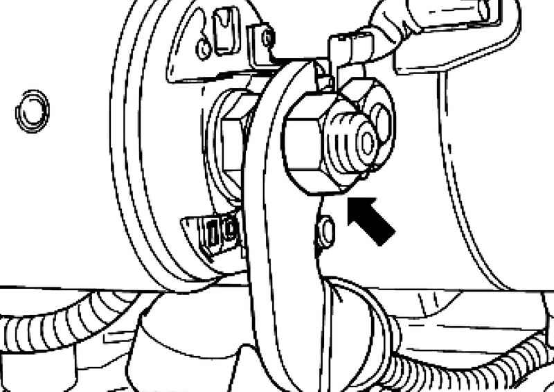
| Fig. 7.48. Fixing nut positive cable of the electromagnetic switch of a starter
|
Unscrew the fixing nut positive cable from the starter solenoid switch (Fig. 7.48).
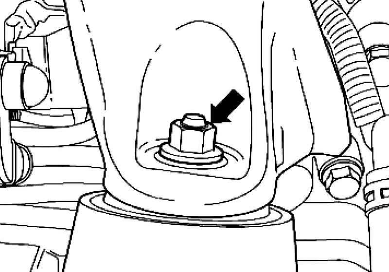
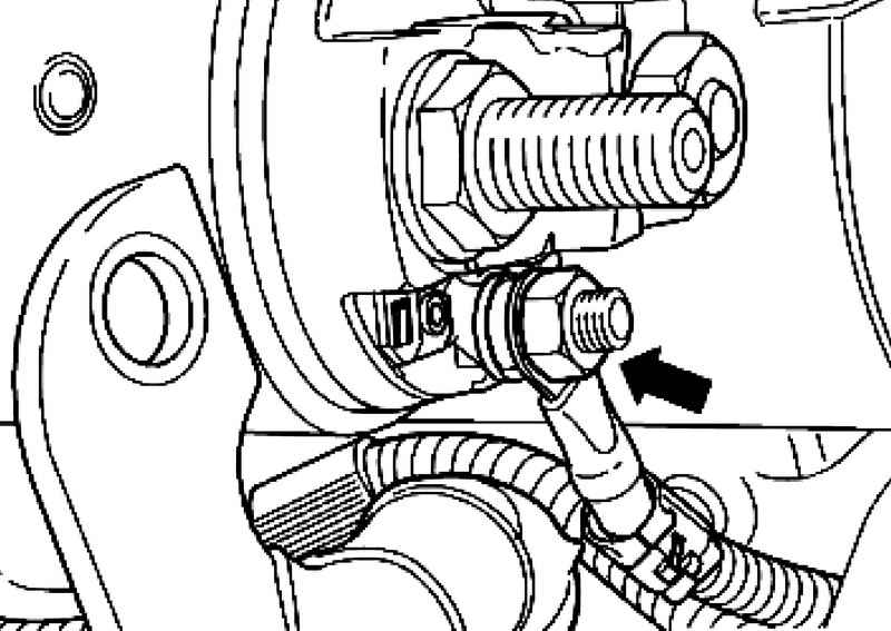
| Fig. 7.49. Fixing nut cable terminals 50 of the electromagnetic switch of a starter
|
Unscrew the fixing nut of the cable terminal 50 from the solenoid starter switch (Fig. 7.49).
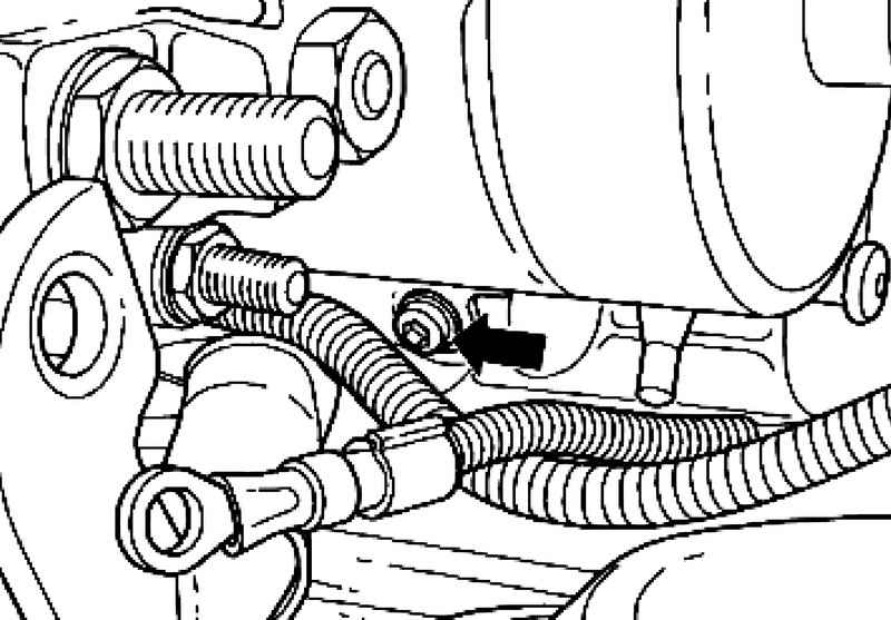
Remove the retaining bolt of the cables and put the cables to the side (Fig. 7.50).
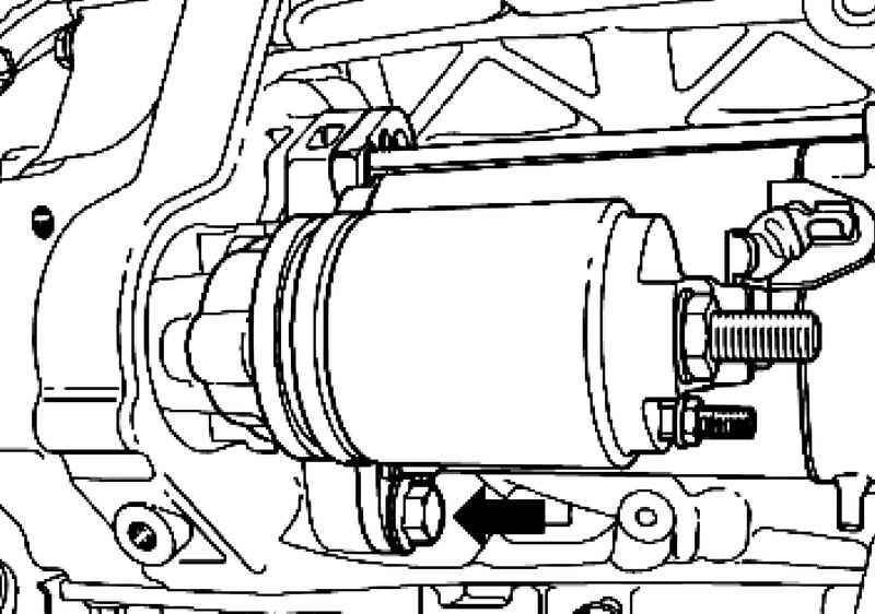
Remove the lower mounting bolt M12h165 starter on the motor side (Fig. 7.51).
Remove upper securing bolt of starter M12h165 on the side of the gearbox (Fig. 7.52). Remove the starter.
Setting Install in reverse order, with the following should be considered. Tighten to the specified torque (see. Table. 7.2).
|