printable version printable version
Removing Engine
NOTE The engine is removed together with the gearbox down. Before removing the fault memory of all control units. |
NOTE To ensure the smooth scrolling of the propeller shaft, set the selector lever in position ?�N?�. Leave the key in the ignition to prevent steering wheel lock. Before dismantling it is recommended to remove the front wheels. In this way, the car can be lowered on the lift, leaving between the casing of the brake discs and the floor a few centimeters. Thus, during operation reach the optimal level of all components in the engine compartment. Some components in the vehicle can not or difficult to disassemble without removing the engine. Therefore, before removing motor is necessary to determine all defective parts and after removal of the engine to replace them. To avoid damage to the parts removed, use the container for removed parts VAG 1698. After the installation of the engine must be returned to all the cable clamps, remove or cut for its dismantling. |
ATTENTION When work must be sure to comply with the requirement to disconnect the battery. |
Turn the ignition and all electrical consumers. First disconnect the battery under the driver's seat. Then disconnect the second battery, which is located in the boot, in the spare wheel well. Remove the left and right wiper arms. Remove the bonnet seal to the front wall.
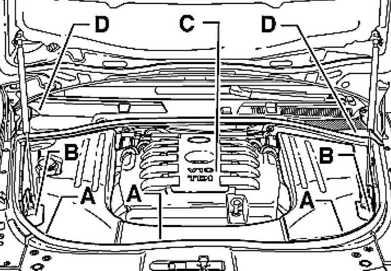
Remove the cover A, B (if any), and C in the engine compartment, and D plenum chamber (Fig. 2.136).
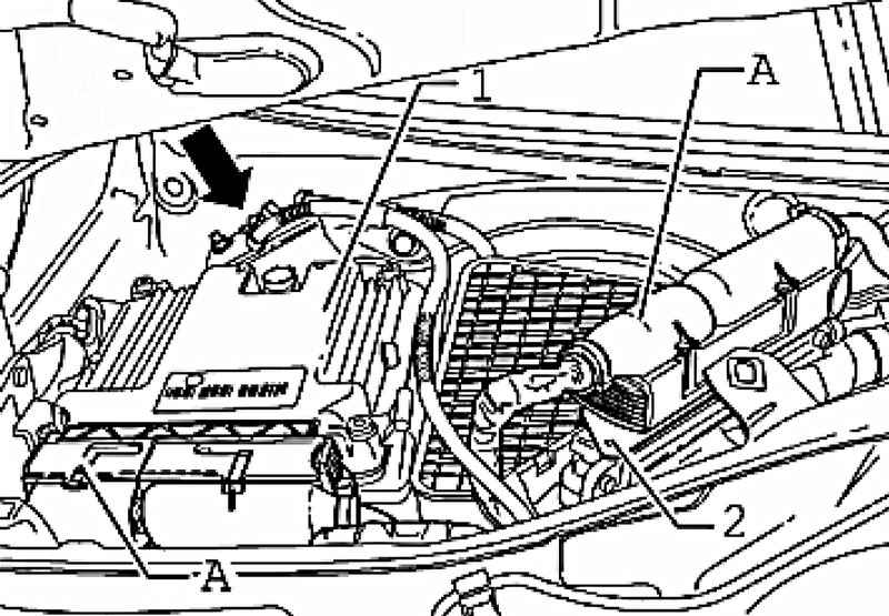
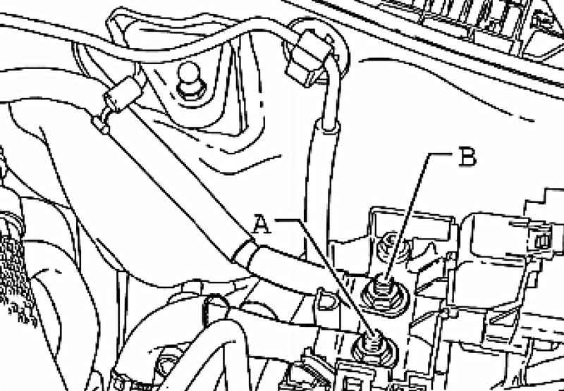
Disconnect the small connector A of engine control unit and turn off the massive terminal wiring harness (Fig. 2.137).
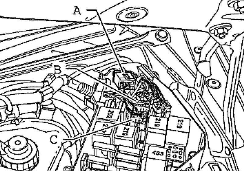
Open the cover of the fuse box, to the left in the plenum chamber and disconnect the connectors A, B and C (Fig. 2.138). Izvlekte harness from plenum chamber and place it on the engine. Remove suction pipe between the air filter and the inlet on both sides.
NOTE If choke connectors pay attention to the instructions of the installation manual. |
Cars with letter designations Engine AYH, BKW
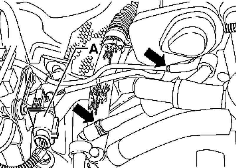
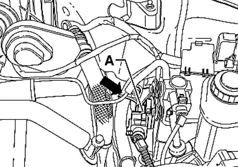
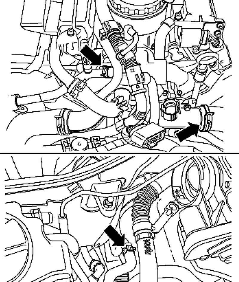
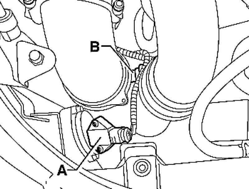
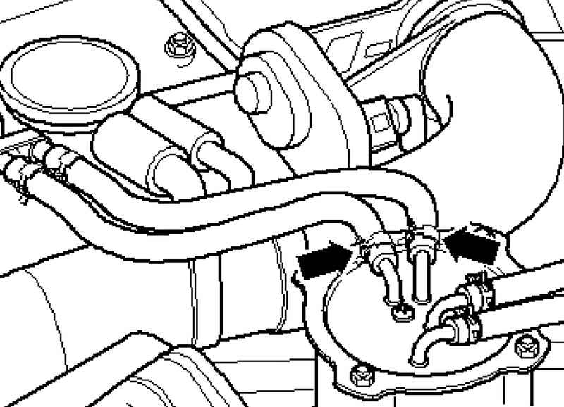
Disconnect vakuumoprovody - arrows - EGR valve and the brake booster, and connector A lambda probe G39 of the first row of cylinders (Fig. 2.139).
Disconnect vakuumoprovod (see. Fig. 2.140) EGR valve and connector A Lambda probe 2 G108 second row of cylinders.
Cars with engines of BLE and BWF
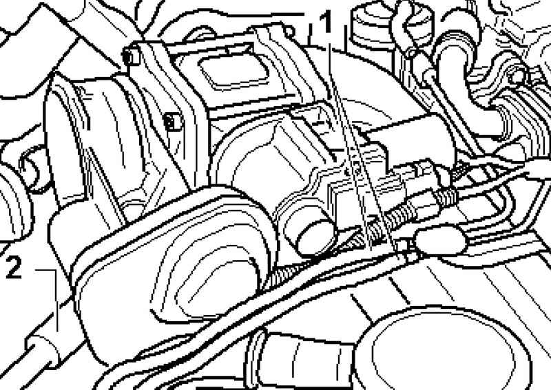
Disconnect the vacuum servo vakuumoprovody 1 bypass cap (the mark on the tubing before disconnecting) and the brake booster 2 (Fig. 2.141).
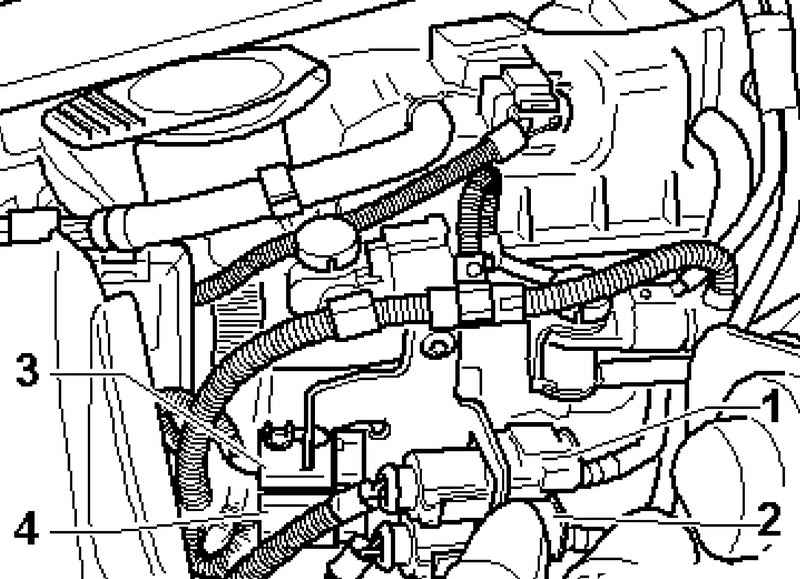
Disconnect following plug connections and disconnect the cable from the following components (Fig. 2.142): 1-6 - pin connector (black) to Lambda probe G39; 2-6 - pin connector (brown) for Lambda probe 2 G108; 3-2 - pin connector (black) for the temperature sensor to the turbocharger G507; 4-2 - pin connector (brown) for the temperature sensor 2 before turbocharger G499.
Continuation of the assembly operations for all vehicles
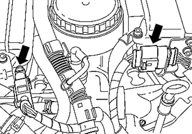
Disconnect plug connections (Fig. 2.143) glow cylinders of the first and second row.
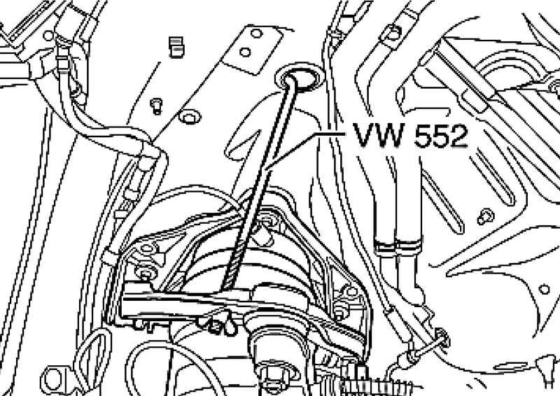
Fix the strut as shown in Figure 2,144, with a spring fixture 552 VW. Turn off the top fixing. shock absorber struts. Remove noise insulation. Evacuate refrigerant. Drain the coolant.
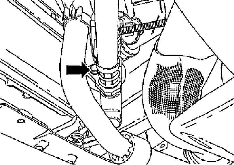
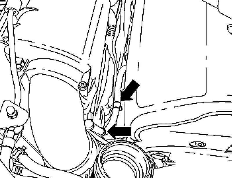
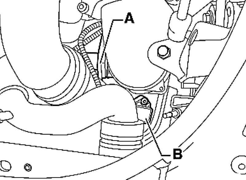
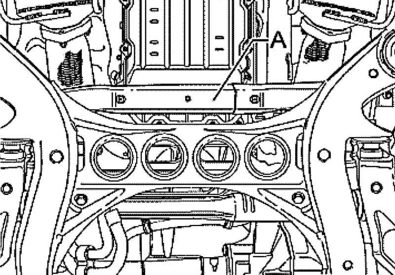
Disconnect the pipe (Fig. 2.145) from the radiator transmission oil at the bottom right. Place a container under the escaping oil. Then disconnect the pipe from the radiator A hydraulic oil at the bottom left. Place a container under the escaping oil.
Remove charge air pipe connecting the first and second row of cylinders (Fig. 2.146).
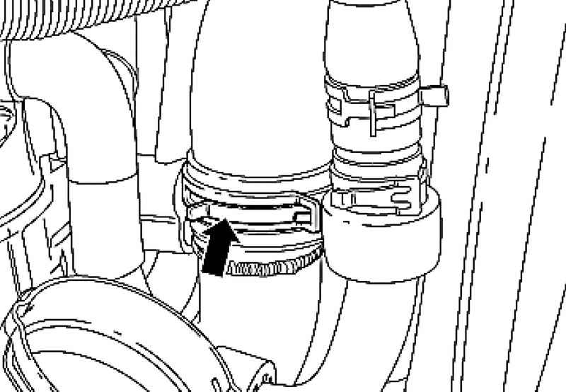
| Fig. 2.147. Clamp connection pipe of the air filter of the first and second row of cylinders
|
Unscrew and remove the clamp (Fig. 2.147) connecting tube of the air filter of the first and second row of cylinders.
Remove the engine cooling system hoses (Fig. 2.148) and place in a way that the installation and removal of the engine were not pinched.
Disconnect the cables A and the starter generator in and put them on the engine (Fig. 2.149).
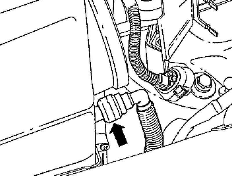
| Fig. 2.150. Clips pipe ventilation system transmission
|
Rasklipsuyte pipeline ventilation system transmission (Fig. 2.150).
| Fig. 2.151. Plug sensor IAT G42-A and the air flow sensor G70-In
|
Disconnect the connector from the air temperature sensor at the inlet G42-A and from the air flow sensor G70-in the first row of cylinders (Fig. 2.151).
| Fig. 2.152. Plug sensor IAT G426-A and the air flow sensor G299-In
|
Disconnect the plug from the mass air flow sensor A - G246-A and from a sensor in the intake air temperature - G299-In the second row of cylinders (Fig. 2.152).
Disconnect the pipe (Fig. 2.153) compressor air suspension on the air filter housing. Remove both the upper part of the air filter up.
| Fig. 2.154. Pipes hydraulic circuit and the air conditioning system
|
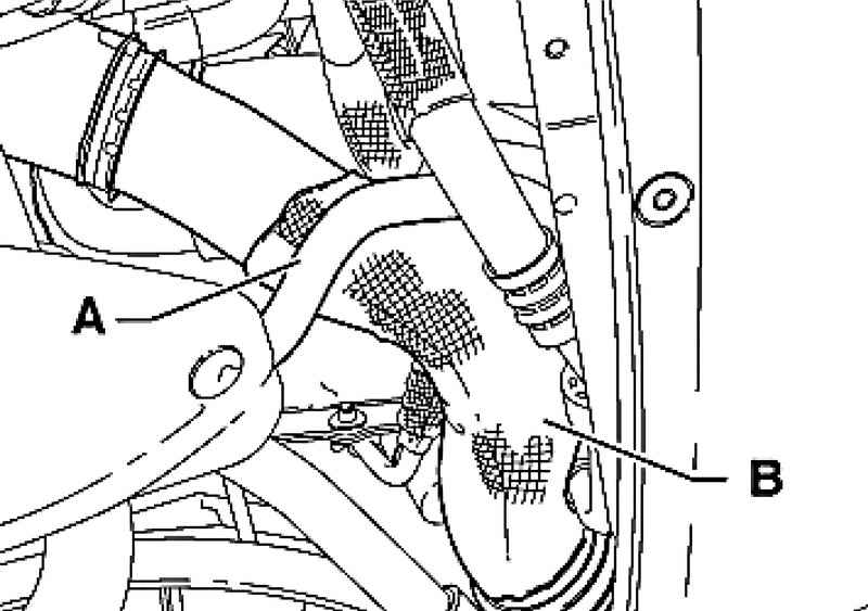
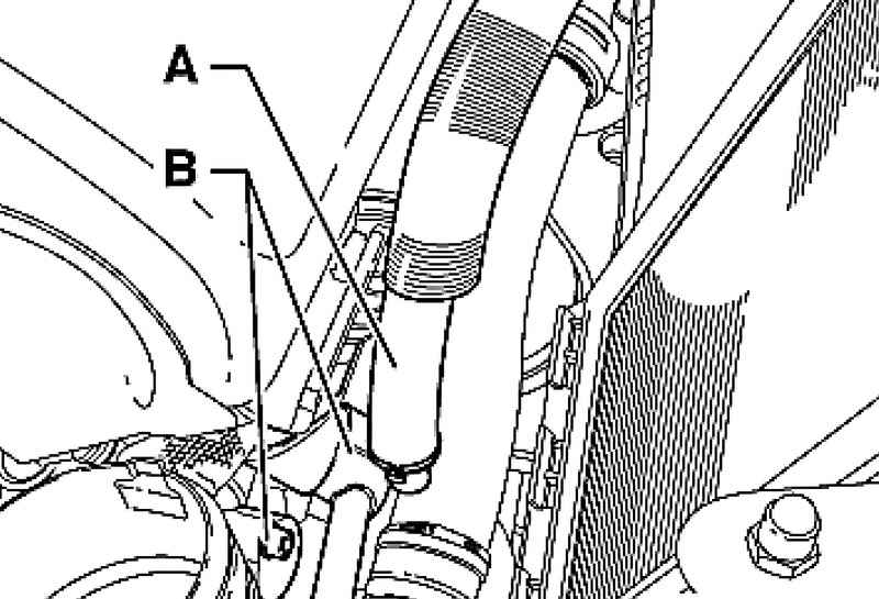
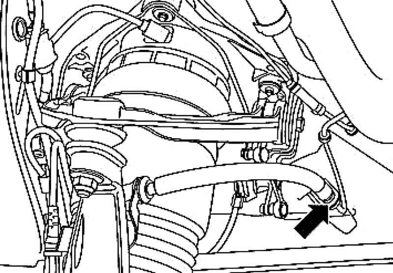
Open the clamp and remove the tube hydraulic A. Put a container under the escaping oil. Remove the tube circuit in the air conditioning system of the air conditioning compressor (Fig. 2.154).
Cars with letter designations Engine AYH, BKW
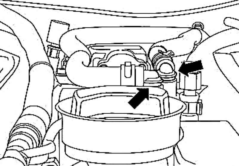
Remove the fuel (see. Fig. 2.155) with the fuel filter. Disconnect the catalytic converter and silencer, remove the exhaust system.
Cars with engines of BLE and BWF
Remove the fuel (see. Fig. 2.156) with the fuel filter. Disconnect the particle filter and exhaust pipe, remove the exhaust system. Continuation of the assembly operations for all vehicles. Remove the heat shield of the steering mechanism and universal joint. Disconnect the connectors on the gearbox and transfer case, remove the cable drive selector lever. Remove the rear driveshaft.
Place a container under the outflow of brake fluid. Disconnect all connectors between body and front axle in wheel niches. Prepare a timeline VAS 6131 for further operation.
NOTE The basic kit car Touareg VAS 6131/6 consists of a support VAS 6131/61 to VAS 6131 / 6-7. For the most visual representation of the working process are mentioned: support 1 (for VAS 6131 / 6-1) - a support 7 (for VAS 6131 / 6-7). |
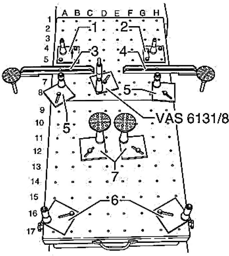
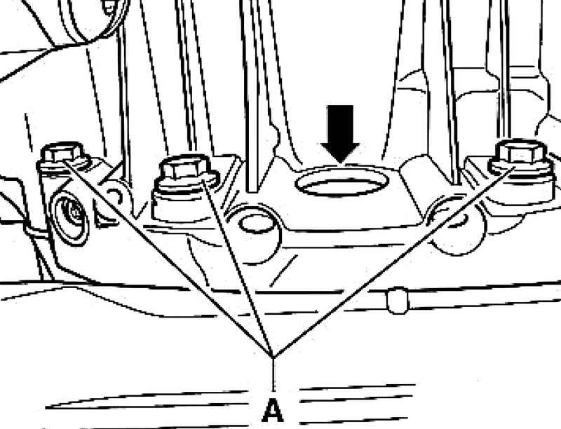
Establish a support 1 on the left and support 2 on the right (arrows show the direction of travel) on the timeline VAS 6131 and tighten the bolts in the following positions: - Left support 1 - A5, B4 and B5; - The right support 2 - G4, H4 and H5. Secure the support 3 and 4 on the pasteboard in the following positions: - Left support 3 - A6 and C6; - The right support 4 - F6 and H6. Remove the dish supports 3 and 4 downwards. Install the support 5 and 6 to the sub-frame for the console transmission to the appropriate position on the lifting table. Engine and gearbox after removing the need to disconnect from each other. Remove shumovibroizolyatsiyu under the oil sump. Remove the starter cable clamps. Unscrew and remove bolts of transmission A.
Through a hole in the oil pan (Fig. 2.160) unscrew six bolts gear. To do this, turn the engine over the damper with counter support T10172 using the supplied bolts and T10172 / 2. Install the support 7 for supporting the transmission to the appropriate position on the timeline and remove the plates of support all the way down.
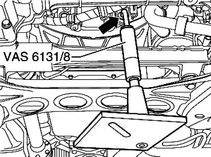
Hook just before the rise of the pasteboard in advance inside-the highest position stop for the V-10, 8 and 6-cylinder engines of the car Touareg VAS 6131/8 in the hole of the flange gear box as shown in Figure 2.161.
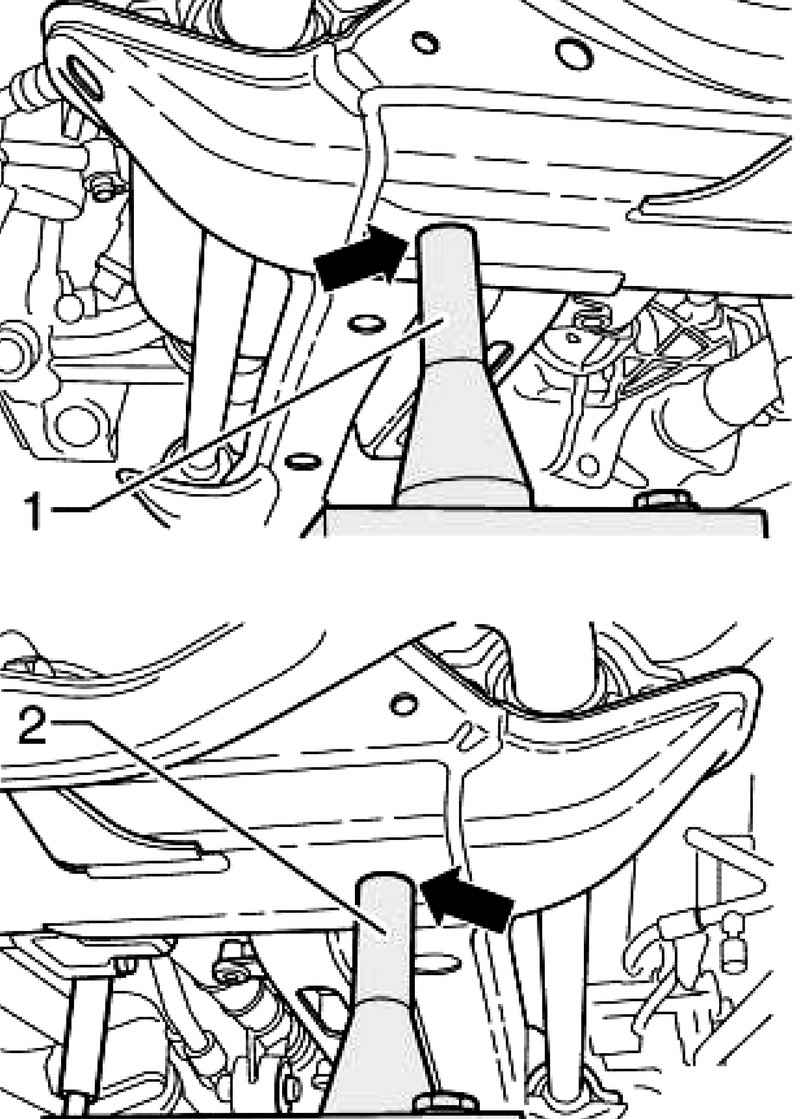
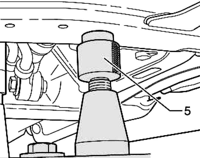
Move horizontally aligned timeline for the power unit. Supports 1 and 2 must enter the left and right of the respective terminals (Fig. 2.162). Simultaneously enter support 6 for a transmission crossmember left and right in the corresponding holes. When all four legs are fixed in foster holes without pressure, if necessary, adjust the height stop for the V-shaped 10-, 8-, and 6-cylinder engines of the car Touareg VAS 6131/8 using the knurled nuts and secure support in the mounting position D7 table. Remove the two plate supports 3 and 4, with a focus in the arms so that you can remove suspended for insurance spring fixture VW 552. Enter the support 5 to the corresponding jacks on a stretcher, if necessary, adjust the height of the supports using the knurled nut.
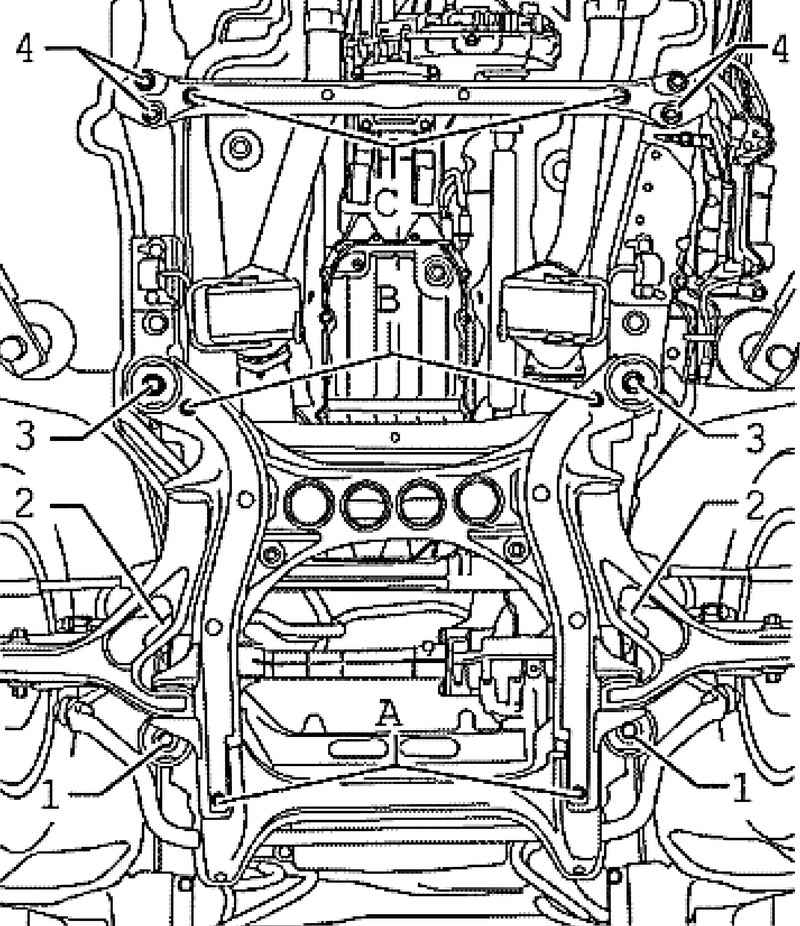
You secure the subframe to the body ( Fig. 2.163 ). Loosen the screws subframe 2 and 3 and cross members 4 transmission.
If the subframe was not fixed, loosen the bolts of the subframe 1 (Fig. 2.164).
NOTE If the subframe is not fixed, it is necessary to make measurements of the axes. Now slowly lower the unit down, continuously monitoring the progress unhindered. |
Installation Instructions Installation is carried out in reverse order.
ATTENTION When all installation work, in particular in the engine compartment, because of the tight layout, consider the following: all types of lines (such as fuel, hydraulic for additives, cooling systems, circuit conditioning systems, brake lines, vacuum tubes), and also necessary to lay electric wires as they were originally laid. Provide sufficient space to all moving or hot components to avoid damage to any kind of lines. |
It is necessary to consider the following: check that the cylinder block mounting sleeves for centering the engine / gearbox, if necessary, insert the plug. Reconnect all tubing, hoses and electrical connectors that were disconnected during removal.
|