add to favorites contacts sitemap
REPAIR MAINTENANCE OPERATION OF MOTOR VEHICLES
Volkswagen Touareg (from 2003 to 2006, the year of issue)

general info. full specifications. diagnostics. hints. tips. tricks
Volkswagen Touareg
Home
 
Volkswagen
Touareg
Operation and maintenance of car
Engine
Transmission
Chassis
Steering Gear
Brakes
Onboard electric
Overview
Generator and starter
Removing and installing starter (6-cyl. Engine with injection 3.2 liter engine and a 3.6 liter FSI, automatic transmission)
Removing and installing starter (8-cyl. Engine with injection 4.2 liter, automatic transmission)
Removing and installing starter, 10-cyl. TDI 4,9 liter engine, automatic transmission
Three-phase generator
Removal and installation of a three-phase generator, air-cooled, 6-cyl. injection engine
Removal and installation of a three-phase generator, 8-cyl. injection engine
Removing and installing voltage regulator
Device combination
Front wiper
Headlights
Tables
Body
diagrams


Hit Counter by Digits


print page printable version

Removal and installation of a three-phase generator, 8-cyl. injection engine


Withdrawal

Contour V-belt 8-cyl. injection engine
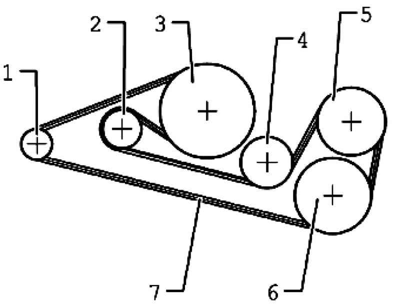
Fig. 7.60. Contour V-belt 8-cyl. injection engine 1 - a pulley belt transmission - three-phase generator; 2 - a tension roller; 3 - a pulley belt transmission - the crankshaft; 4 - discharge roller; 5 - a pulley belt transmission - air-conditioning compressor; 6 - a pulley belt transmission - vane pump Power Steering; 7 - ribbed belt - three-phase generator, vent clip, air conditioning compressor, power steering vane pump mechanism, crankshaft, water pump and a tension roller


Remove the engine.

Loose V-ribbed belt
Fig. 7.61. Loose V-ribbed belt


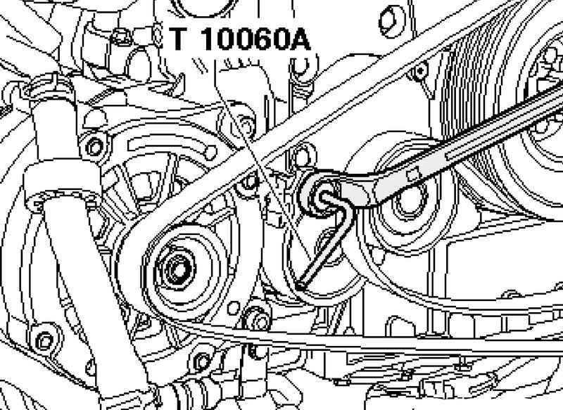
Loosen the serpentine drive belt tension element provernuv using box wrench with SW 19 (Fig. 7.61).
Fix the tension element by means of locking pin T10060 A.

Plug wire DF
Fig. 7.62. Plug wire DF


Disconnect the cable connector DF (Fig. 7.62).

Protective cap
Fig. 7.63. Protective cap


Remove the protective cap (Fig. 7.63).

Attaching the wires B +
Fig. 7.64. Attaching the wires B +


Remove the wire from the generator B + (Fig. 7.64).

Holder pipes of the cooling system
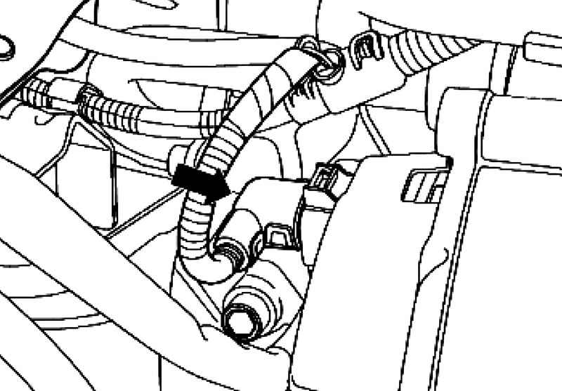
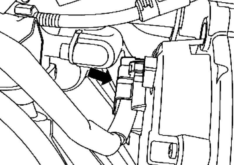
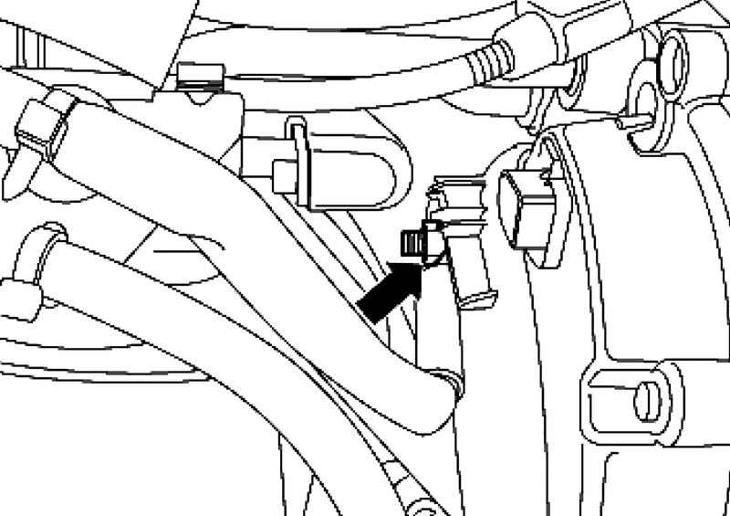
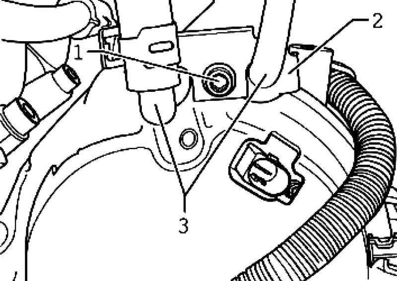
Fig. 7.65. Holder pipes of the cooling system


1 Remove the fixing bolt and remove the holder 2 tubes of the cooling system from the generator (Fig. 7.65).
Remove the tube cooling system 3 of the generator.

Fixing screws M8h90 generator
Fig. 7.66. Fixing screws M8h90 generator


Remove the fixing bolts M8h90 generator (Fig. 7.66).

Setting
Install in reverse order, with the following should be considered.
Tighten to the specified torque.
Replace seals coolant tubes.


« previos page
Removal and installation of a three-phase generator, air-cooled, 6-cyl. injection engine
next page »
Removing and installing voltage regulator

Copyright © 2010 AutoManuals.biz. Trademarks belong to their respective owners. All rights reserved.