printable version printable version
Dismantling of the drive shaft
Removing the external hinge Remove both hinge clamps from the anther. Remove the boot from the external hinge.
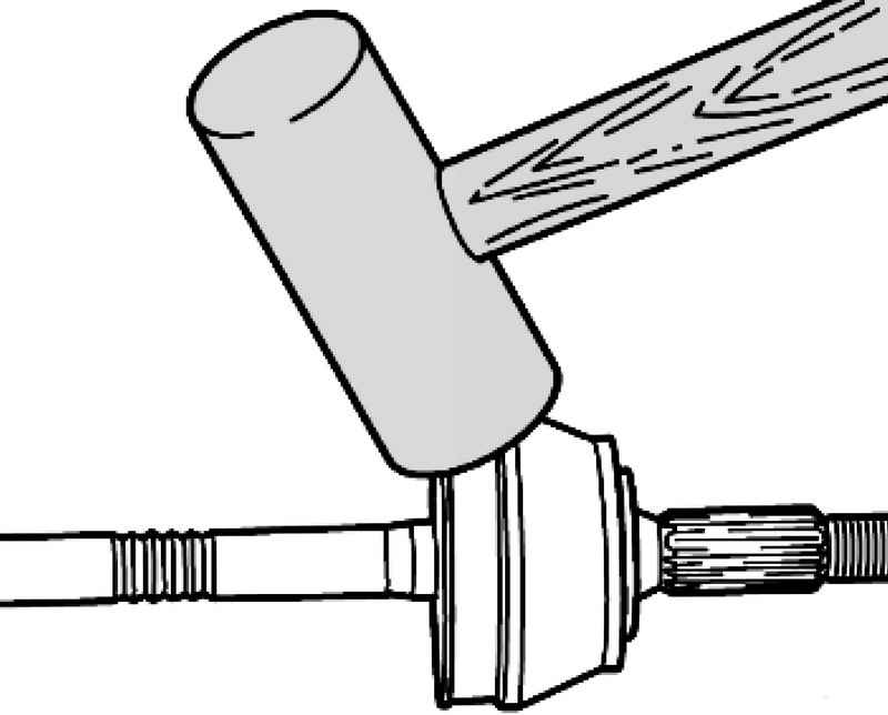
Separate the outer joint from the drive shaft, a strong blow to the hinge with a plastic hammer (Fig. 3.179).
Removing the internal hinge Remove both hinge clamps from the anther. Remove the boot from the internal hinge.
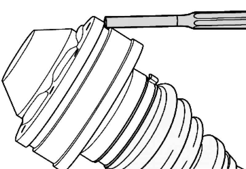
| Fig. 3.180. Removing the cover of the internal hinge
|
Remove the lock ring using pliers for snap rings VW 161 A.
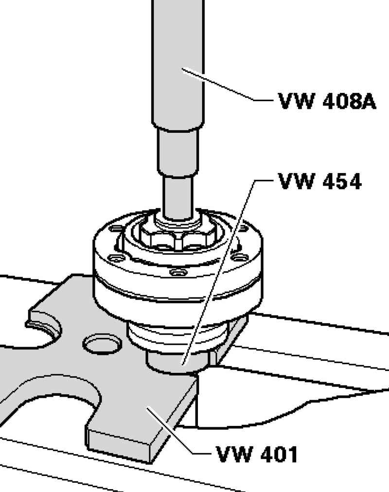
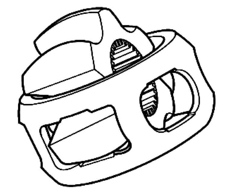
| Fig. 3.181. Pulling out of the internal hinge of a power shaft
|
Extract the internal hinge of a power shaft as shown in the figure. At the same time, hold the drive shaft (Fig. 3.181).
NOTE The internal hinge disassembled for inspection impossible. |
Checking the external hinge Hinge be disassembled for replacement of grease is very dirty, or if you need to check the raceway balls for wear and damage.
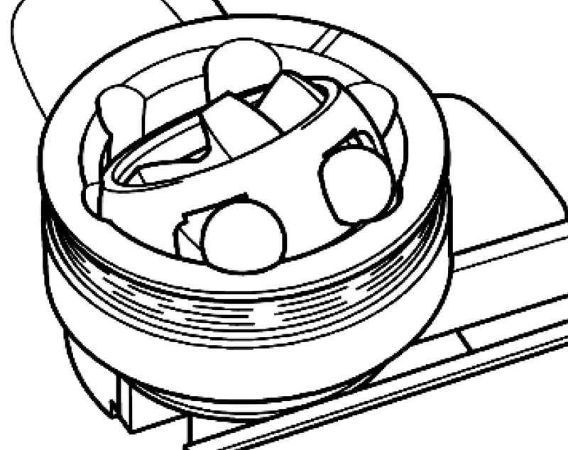
Withdrawal Before dismantling, mark the position of the sleeve with respect to the spherical body and the separator using electrophotography or honing bar. Turn spherical sleeve and the separator. One by one, remove the balls.
Turn the sleeve segment of one of the windows of the separator (Fig. 3.183). Shake out the plug from the separator. 6 balls each hinge belong to one group of admission. Axle spindle, sleeve, separator and balls check for shallow depressions (surface defects), and scoring. Too much lateral play in the joint can be seen by the beating when the load changes, in such cases the joint must be replaced. Have pastes and raceways the balls is not a reason to replace the joint.
Setting Enter hinge housing half of the total amount of grease (60 grams). Insert the separator with the sleeve in the joint housing. Note the large chamfer on the inner diameter of the ball sleeve and the inner diameter of the separator installation must be directed to the shaft. Insert one by one opposing balls, and the need to restore the original position of the spherical hub shell with respect to the separator and the hinge. Spread the rest of the grease in the seal cuff.
|