printable version printable version
Removal and installation of a three-phase generator, air-cooled, 6-cyl. injection engine
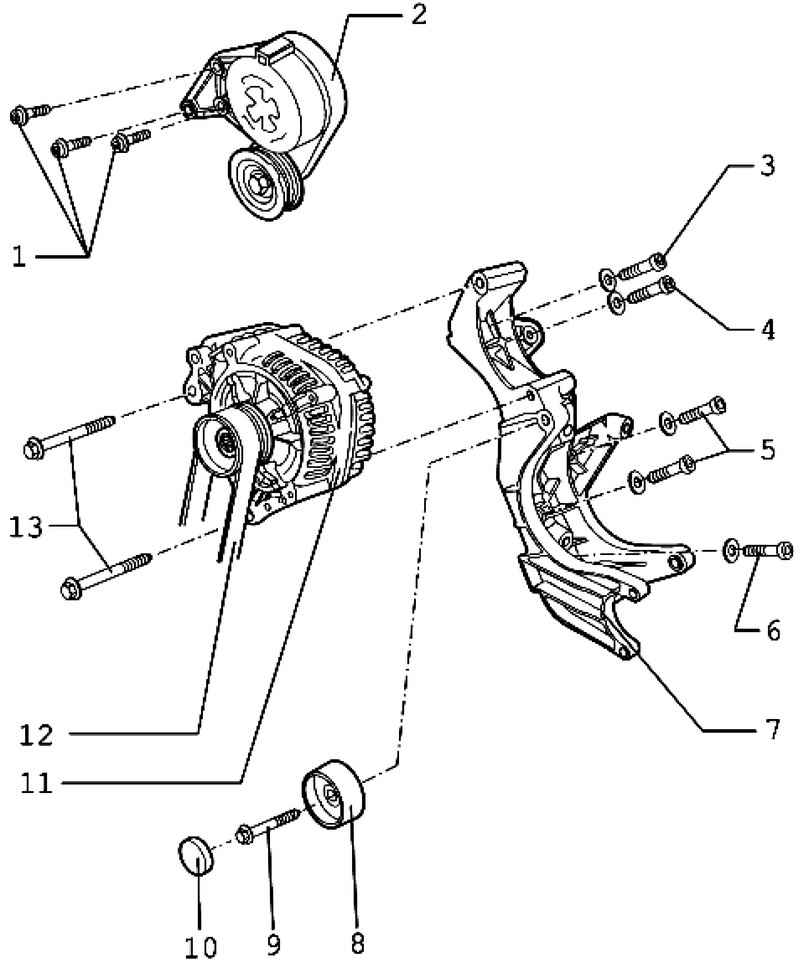
| Fig. 7.53. Components of the three-phase generator, air-cooled (6-cyl. Engine with injection): 1 - a bolt with the Allen hockey; 2 - a tension roller; 3 - a bolt with the Allen hockey; 4 - bolt and washer; 5 - screws with hexagon socket with washers; 6 - bolt and washer; 7 - the holder; 8 - discharge roller; 9 - pin with hexagon; 10 - cap; 11 - three-phase generator; 12 - ribbed belt; 13 - hexagonal bolts with collar
|
Withdrawal Disconnect the battery.
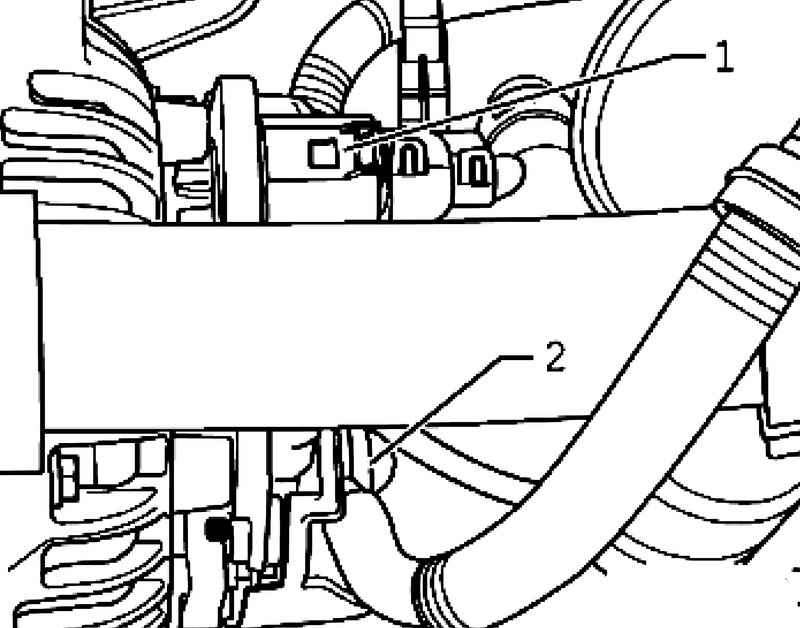
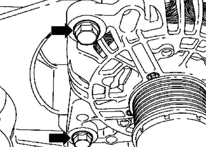
Disconnect connector wire DF 1 and remove the protective cap 2 (Fig. 7.54).
ATTENTION Before removing, mark direction of travel and the upper side of the V-ribbed belt with chalk or marker. When installing the proper direction of movement and position of the sides of the belt. Changing the direction of movement or parties formerly operated V-belt is damaged. |
Remove the air ducts above the radiator.
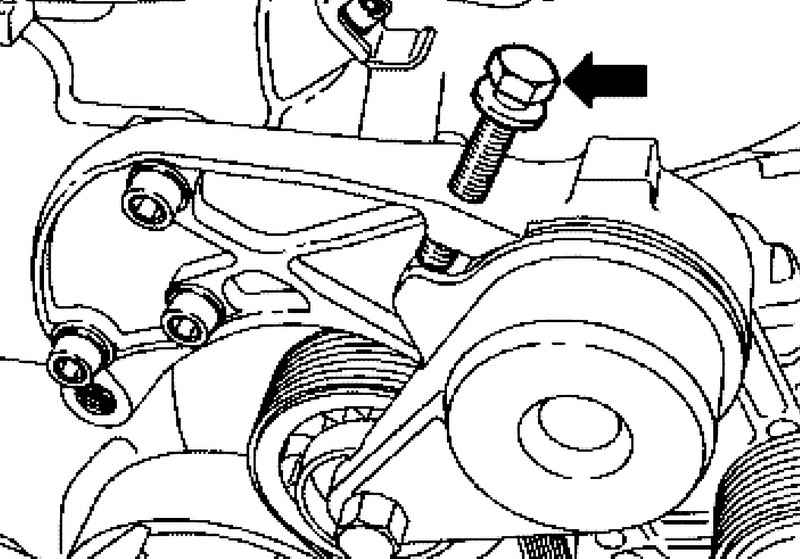
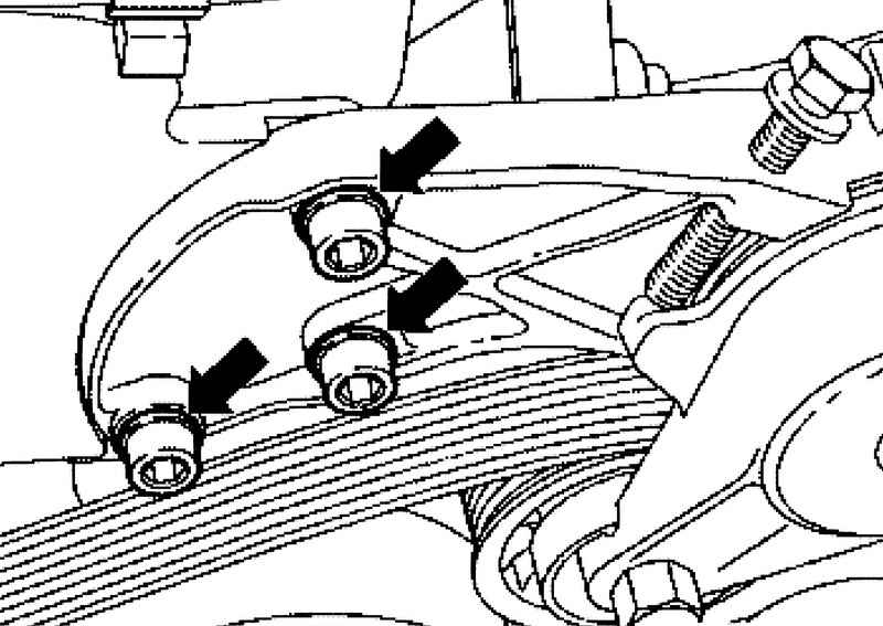
Screw support bolt into the threaded hole M8h50 tension roller so that you can remove the V-ribbed belt (Fig. 7.56).
ATTENTION Housing tension roller may be damaged. Tighten the hex bolt too deep into the body of a tension roller can damage the body. Calculate the depth of the tightening of the hex bolt, it is only necessary to remove the V-belt. |
Remove the serpentine belt with tension roller.
Setting Install in reverse order, with the following should be considered.
ATTENTION When installing the V-ribbed belt previously operated observe marked during removal direction. Check the fastening of all units (alternator, air conditioning compressor, vane pump). When installing the belt in the proper position on the V-belt pulleys. Check whether the loosened the support bolt M8x50 from the tensioning pulley.
|
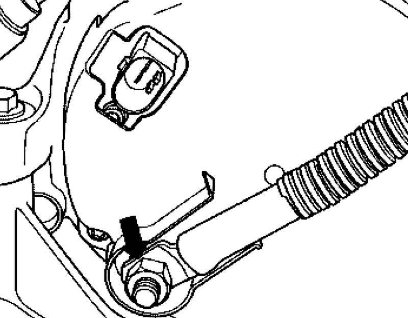
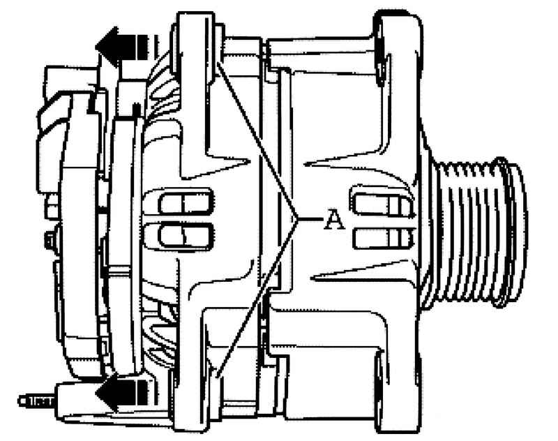
Gently A clear threaded sleeve about 4 mm in the direction of arrows from the housing of the generator (Fig. 7.59). Tighten to the specified torque Connect the battery. Start the engine and check the progress of the belt.
|