printable version printable version
Removal and installation of elements of the cooling system
ATTENTION When you open the expansion tank from it can go hot steam. in order to avoid eye injuries and scalding, put on goggles and special clothing. Cover bull cloth and gently open it. |
ATTENTION In any assembly work, particularly in the engine compartment due to the compact layout, consider the following. Motorways of all kinds (such as fuel, hydraulic absorber, activated carbon, cooling systems, circuit conditioning systems, brake lines, vacuum hoses) and electrical wiring must be routed as they were originally laid. |
Provide space for all moving or hot components.
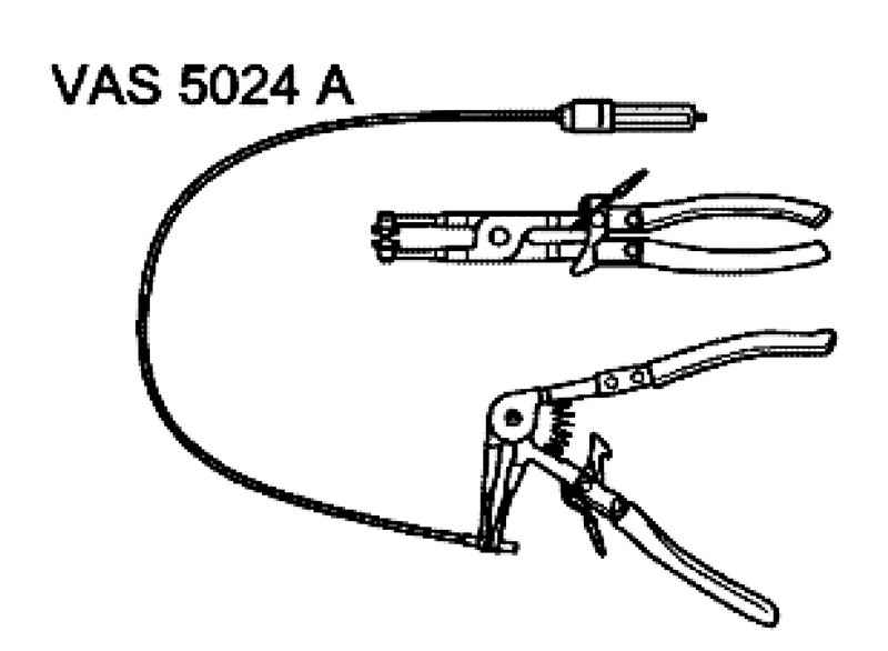
NOTE Hose connections are secured with spring clips. When repairing only use spring clamps. |
For the installation of spring clamps is recommended to use pliers for spring clamps VAS 5024 A (Fig. 2.227). When installing, route the water hoses on pulling them. Make sure that they do not touch other components (observe markings on the pipe and radiator hose).
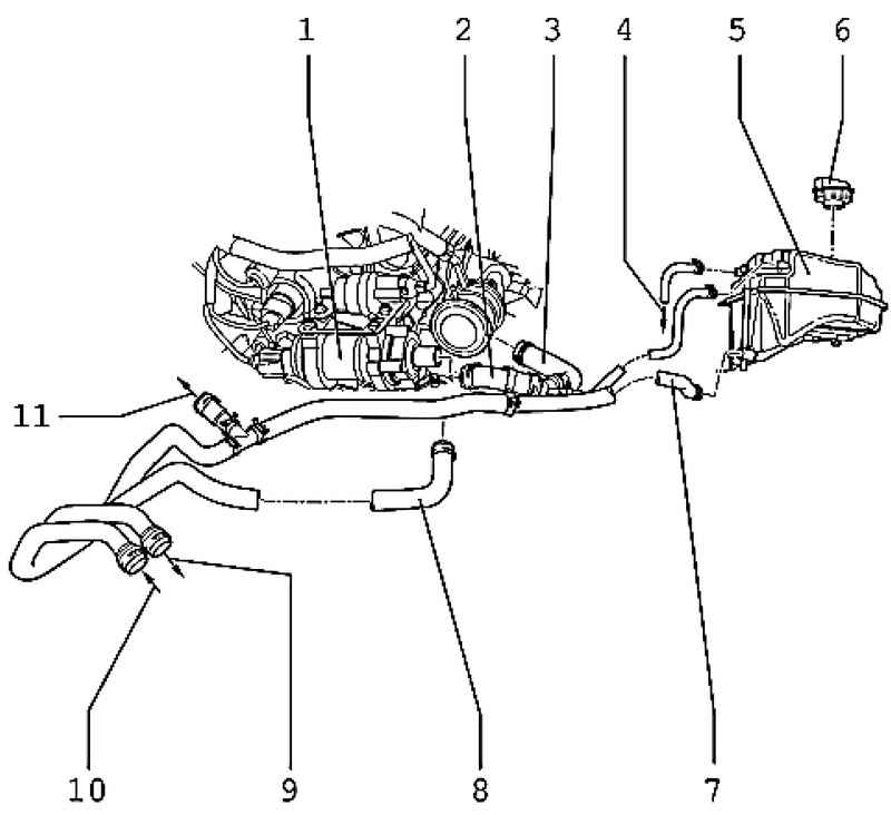
The cooling system installed on the body
| Fig. 2.228. The elements of the cooling system, installed on the back of: 1 - circulation pump coolant V51; 2 - coolant hose; 3 - coolant hose; 4 - from the radiator; 5 - expansion tank; 6 - a cover; 7 - coolant hose; 8 - coolant hose; 9 - the heat exchanger of a heater; 10 - the heat exchanger of the heating system; 11 - to the thermostat housing
|
ATTENTION In any assembly work, particularly in the engine compartment due to the compact layout, consider the following. Motorways of all kinds (such as fuel, hydraulic absorber, activated carbon, cooling systems, circuit conditioning systems, brake lines, vacuum hoses) and electrical wiring must be routed as they were originally laid. Especially when installing the cooling system hoses and to prevent damage, should pay attention to the availability of sufficient space between the hoses themselves, as well as all moving or hot components.
|
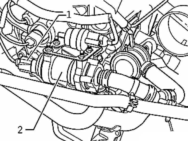
Place the pump run-coolant V51
The pump coolant V51 2 fixed to the cylinder head by a solenoid valve 1 activated charcoal canister N80 damping ring to the bracket.
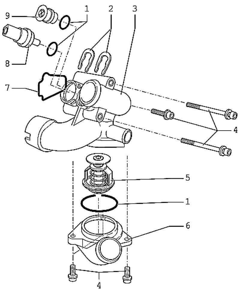
Thermostat Housing
| Fig. 2.230. Arrangement thermostat housing: 1 - O-ring; 2 - mounting bracket; 3 - the thermostat; 4 - a bolt 8 Nm; 5 - the thermostat; 6 - a connecting pipe; 7 - a sealing ring; 8 - the coolant temperature sensor G62; 9 - cork
|
Provide space for all moving or hot components.
ATTENTION In any assembly work, particularly in the engine compartment due to the compact layout, consider the following. Motorways of all kinds (such as fuel, hydraulic absorber, activated carbon, cooling systems, circuit conditioning systems, brake lines, vacuum hoses) and electrical wiring must be routed as they were originally laid. |
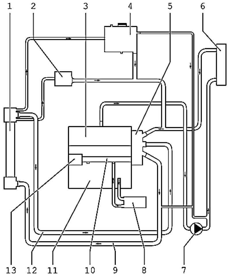
Plan for connecting coolant hoses
| Fig. 2.231. Wiring coolant hoses 1 - radiator; 2 - oil cooler; 3 - cylinder head; 4 - a broad tank; 5 - the thermostat; 6 - the heating heat exchanger; 7 - coolant circulation pump V51; 8 - oil cooler; 9 - coolant hose, the top; 10 - the coolant supply tube; 11 - the block of cylinders; 12 - coolant hose, bottom; 13 - water pump
|
|