printable version printable version
Removal and installation of injectors
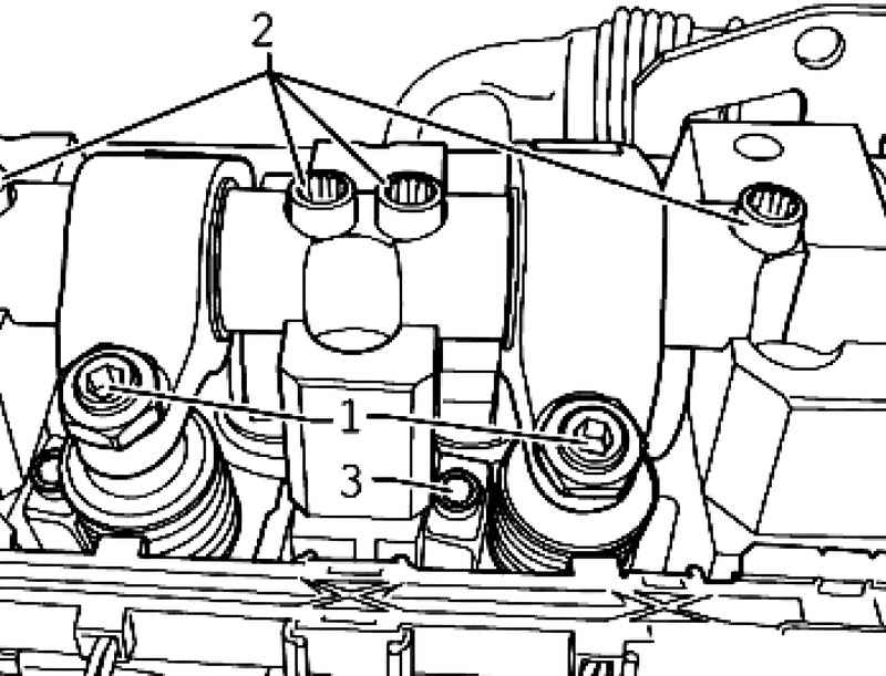
Withdrawal Remove the soundproof cover and cylinder head cover corresponding cylinder head. Rotate the crankshaft until the pair of cams, respectively, mounted or dismounted unit injectors are not uniformly show up. Loosen the lock nuts of the adjusting screws 1 and remove the adjusting screws so until the corresponding rocker rests on the spring pusher injectors.
Unscrew the fastening screws 2-axis roller levers from outside to the inside using a nozzle end 3410 and remove the roller lever valves (Fig. 2.291). Unscrew the fastening bolt 3 via spacers T10054 end nozzle and remove the spacer. Disconnect plug injectors with a screwdriver. Easy hold finger to the back of the plug in order to avoid skewing.
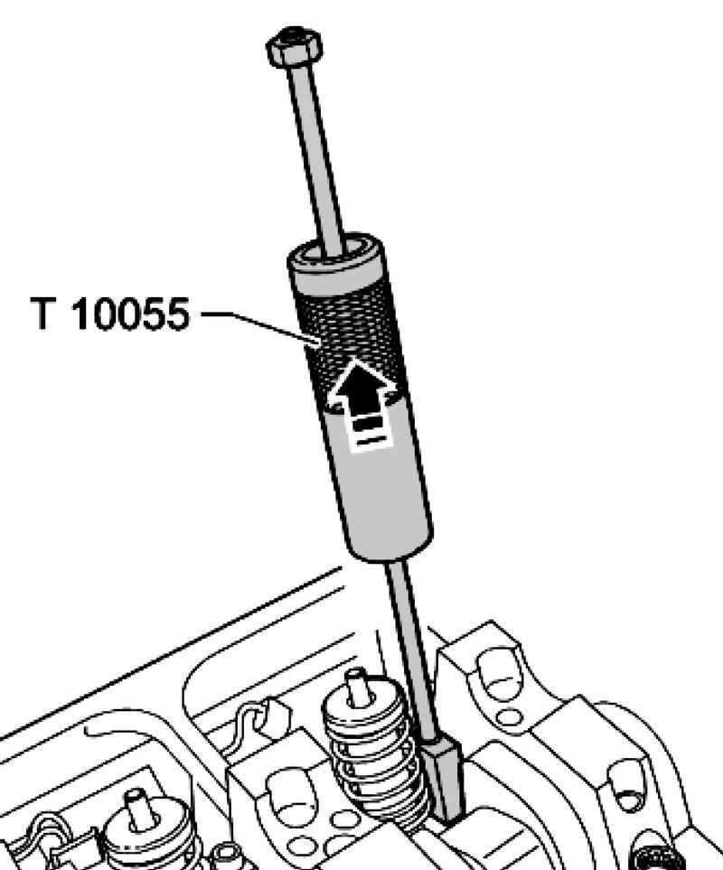
Install the puller T10055 in place spacers in the side groove of the unit injector (Fig. 2.292). Gently tapping, remove the pump nozzle upwards from its slot on the cylinder head.
Setting In all the works related to the adjustment of the pump-injector, it is necessary to replace the adjusting screw in the yoke and screw with ball head injectors.
NOTE When installing a new unit injector is necessary to replace the appropriate rocker arm adjusting screw. |
The new injectors are supplied with O-rings and heat sealing. When reusing the injectors need to replace the seals of circular cross section and heat-insulating seal. Before installing the pump nozzle check the planting of three O-rings, seals and thermal insulation retaining ring.
NOTE O-rings should not be twisted. |
Lubricate the O-ring and carefully install the pump nozzle into the slot on the cylinder head. Evenly pressing, insert the pump nozzle, all the way into the socket on the cylinder head. Install the spacer in the side slot injectors.
NOTE If the pump injector is not at right angles to the spacer, the fixing bolt can unscrew, resulting in damage to the unit injector or cylinder head. |
Install unit injector as follows. Screw the fastening screws in the spacer until the pump nozzle can be easily rotated.
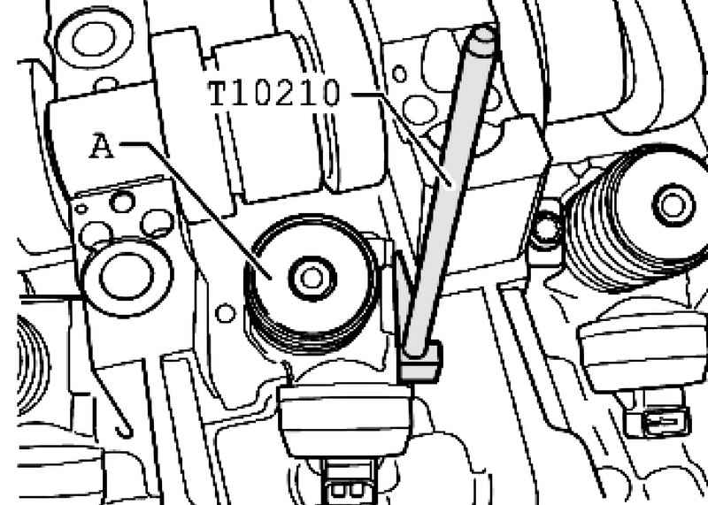
Set the template T10210 bed between main bearing and the pump-injector (Fig. 2.293). Turn the pump nozzle from the hand in the direction of the pattern. Additionally, align, if necessary, pump-nozzle and tighten the mounting bolts in the following way: 12 Nm + 3/4 rev. (270 ?°) (additional tightening may be carried out in several stages). Install the new axis of roller levers and tighten the new mounting bolts as follows. First, domestic, then both external by hand. Then, in the same sequence with torque 20 N ?· m + 1/4 vol. (90 ?°).
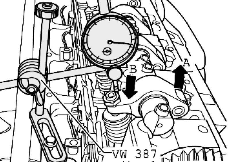
Set micrometer adjusting screw unit injector as shown in Figure 2.294. Rotate the crankshaft in the direction of rotation of the motor shaft until the roller rocker arm will not appear at the highest point. Side roller arrow A, located at the highest point. Micrometer arrow V, is at the lowest point. Remove the mic. Now wrap the adjusting screw to compress the spring injectors until tangible resistance is felt (unit injector screwed up to the stop).
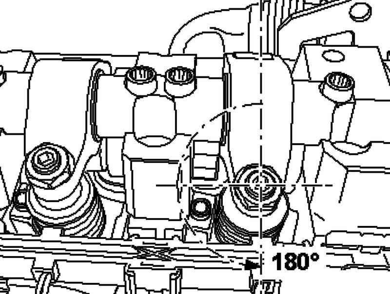
Remove the adjustment screw from the "twisted all the way" to 180 ?° (Fig. 2.295). Keep adjusting the screw in this position and tighten the locknut to a torque of 30 Nm. Install the plug injectors and install the cylinder head cover and sound insulation cover.
|