printable version printable version
Removing and installing subframe
Withdrawal Subframe lifted with the lifting table scissor. At the front point of the engine support bracket must be set shorter, safety bolts. The subframe is removed along with. steering, drive the front axle, lower arm and the wheel hub bearing housings. Air spring / damper struts with support brackets and upper suspension arms are by car.
ATTENTION Switchable stabilizers before starting work you must turn. Otherwise inadvertent inclusion of stabilizers can lead to injury. |
Turn the hydraulic system disconnected stabilizers. Unscrew the wheel bolts. Raise the vehicle. Remove the front wheels.
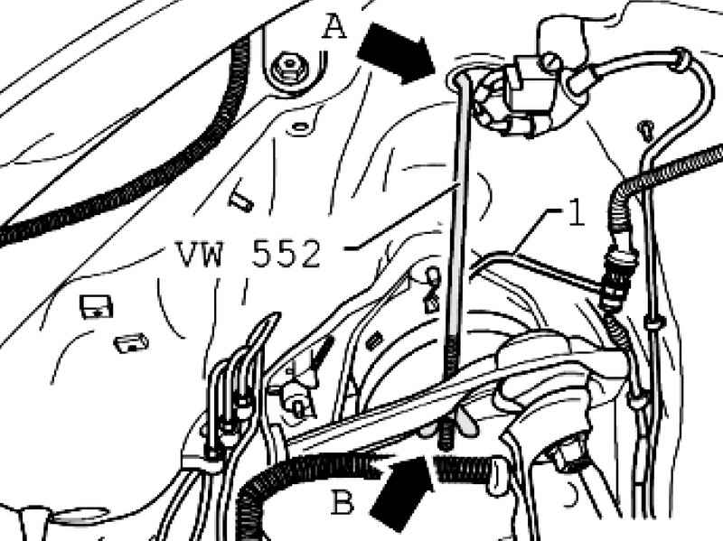
Establish a spring fixture VW 552 on both sides of the car in the top hole A and the wheel house to the upper suspension arm B (Fig. 4.51). Lightly tighten the lever so as not to damage the ball pin of the hinge suspension.
The wheel housing, disconnect the brake hose from the brake lines. Disconnect all electrical wires between the body and suspension. Remove noise insulation below engine / gearbox.
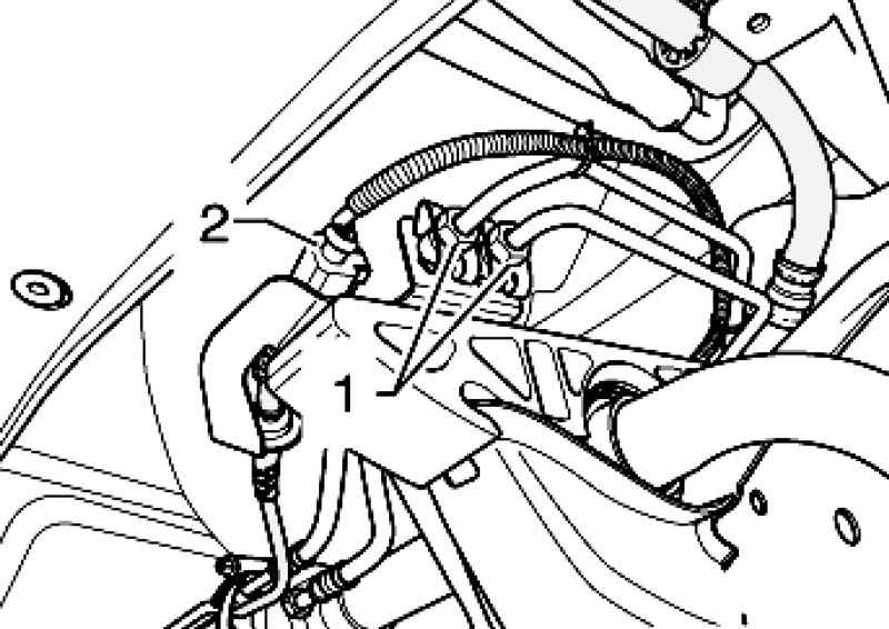
Remove the pressure and drain pipes 2 from the steering mechanism. Remove the propeller shaft from the front final drive and tie.
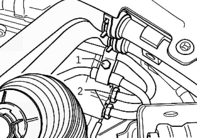
Disconnect both hydraulic lines and electrical connections 1 2 (Fig. 4.54). When installing the pipes do not mix. Check whether the label "in the direction of" the front pipe. If not, apply a new one. Loosening pipes, they hold open-end wrench.
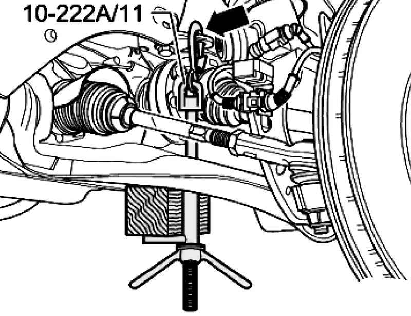
Insert rods 10-222 A / 11 in the hinge bracket motor for the right and left sides (Fig. 4.47).
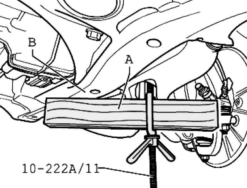
Insert a wooden block A, the length of about 300 mm rod bracket 10-222 A / 11 (Fig. 4.48). This bracket should be sent back. Tighten the clamp rods, wooden sticks for this must rely on the bracket mounted units B. Place the tip of Jacks in the rack for the engine and gearbox VA G 1383 A.
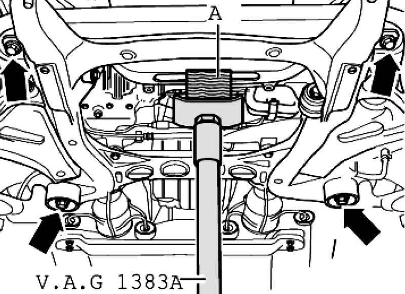
Set the rack for the engine and gearbox VA G 1383 A under the engine bracket and press gently (Fig. 4.55). Secure the subframe. Unscrew the bolts of the subframe. Loosen the connecting rod on the left and right of the stabilizer. Lower subframe via rods 10-222 A / 11, about 50 mm. Use two bolts M14x1,5x90, such as bolts ?„–104 01 281 to secure the motor mount on the left and the right. Remove the rack for the engine and gearbox VAG 1383 from under the arm of the engine.
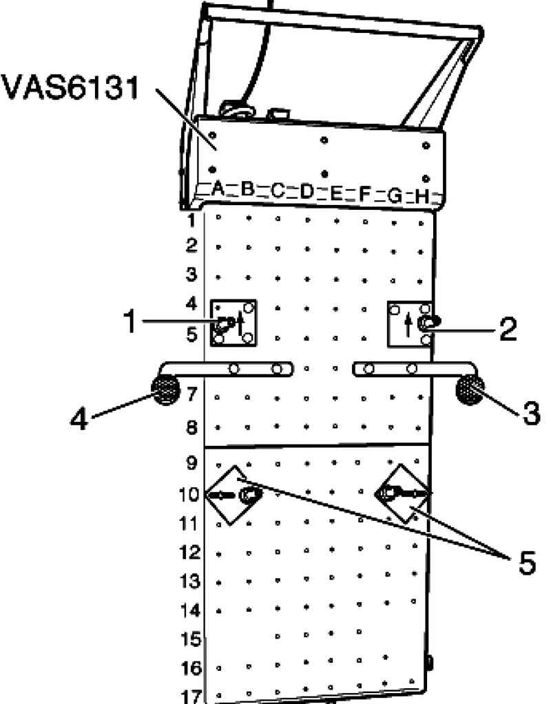
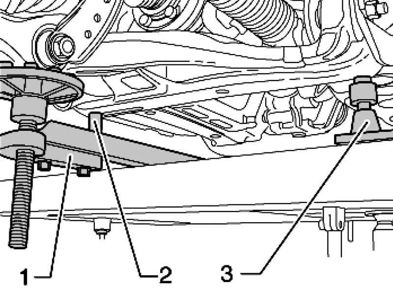
| Fig. 4.56. Scissor table: 1 - Left support VAS 6131/61; 2 - the right support VAS 6131/62; 3 - support for Bush left VAS 6131/63; 4 - support for the suspension of the right VAS 6131/64; 5 - support VAS 6131/65
|
Screw the support to the lifting scissor table, as shown below (Fig. 4.56).
| Fig. 4.57. Set on a stretcher lift table: 1 - support for Bush left - VAS 6131/63; 2 - support the left - VAS 6131/61; 3 - support - VAS 6131/65
|
Remove stems 10-222 A / 11 from the stretcher.
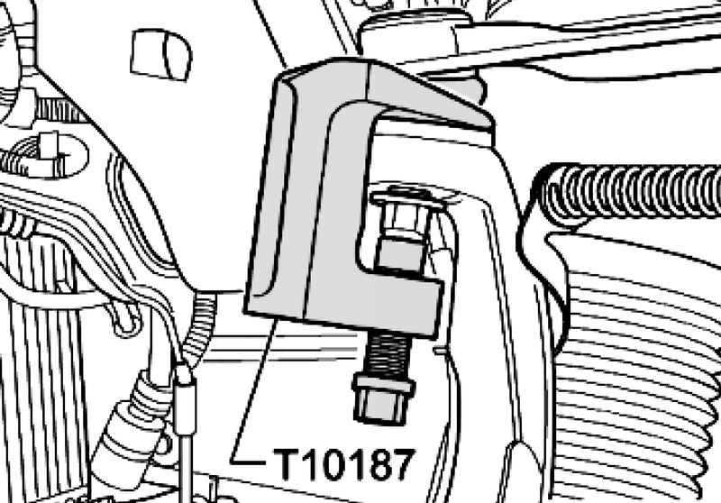
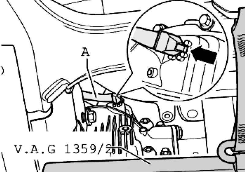
Carefully remove the conduit for venting A, with the main front transmission (Fig. 4.58). Now slowly lower subframe. Watch out for those to happen smoothly.
Setting Install in reverse order, with the following should be considered. Fixing bolts of the PTO shaft always replace Remove stems 10-222 A / 11 from the stretcher. Install the universal joint on the steering gear and tighten the bolt torque. If there is, you set the screen on the steering Install the front wheels On cars with switchable stabilizers bleed stabilizers. Bleed the brake system. After installation, perform a test drive, if the rectilinear motion of the steering wheel is not straight, you need to axle measurement.
|