printable version printable version
Switchable stabilizer
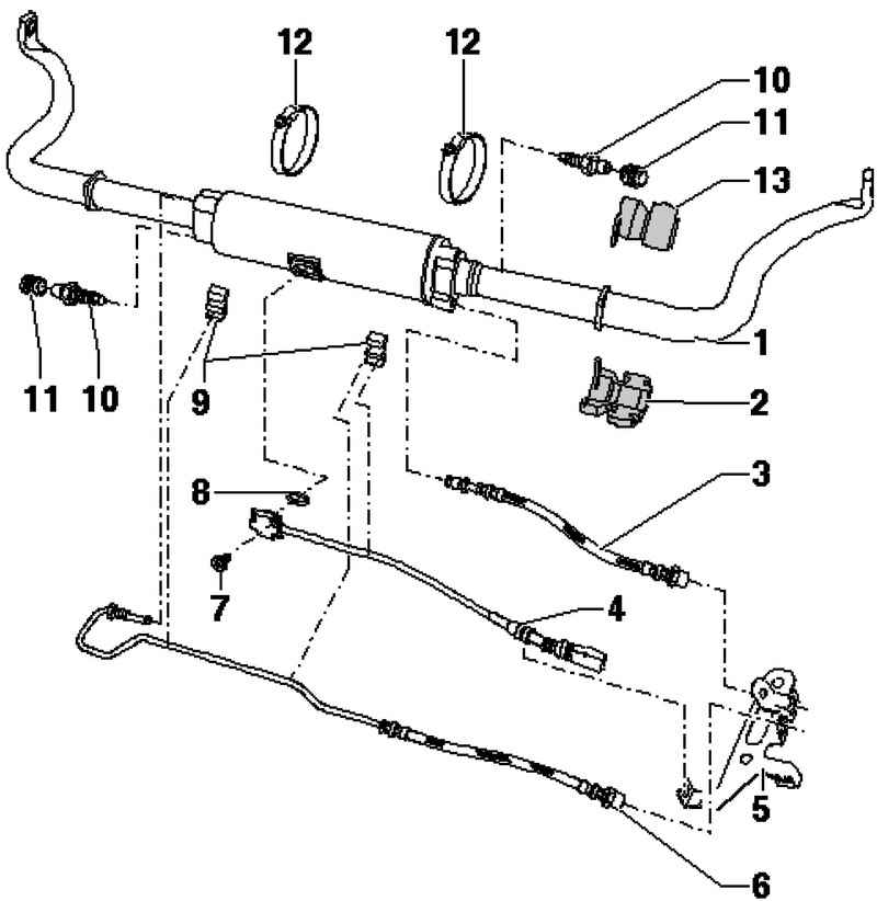
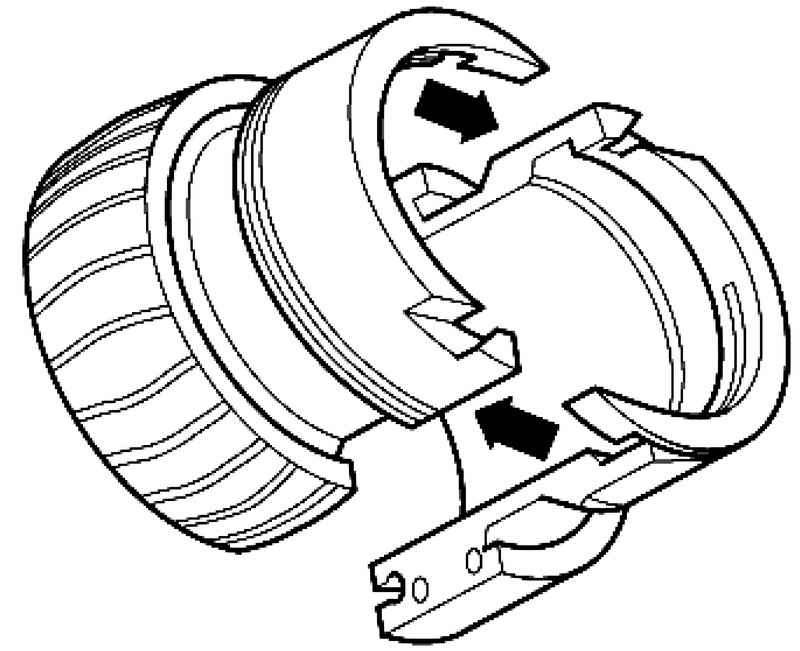
| Fig. 4.59. Components of the stabilizer to be disconnected: 1 - detachable front stabilizer; 2 - the bearing of a stabilizer; 3 - hydraulic line; 4 - the gauge of the front suspension stabilizer off; 5 - the holder; 6 - hydraulic line; 7 - Allen screw; 8 - a sealing ring; 9 - the holder; 10 - nipple for pumping; 11 - cap; 12 - a collar
|
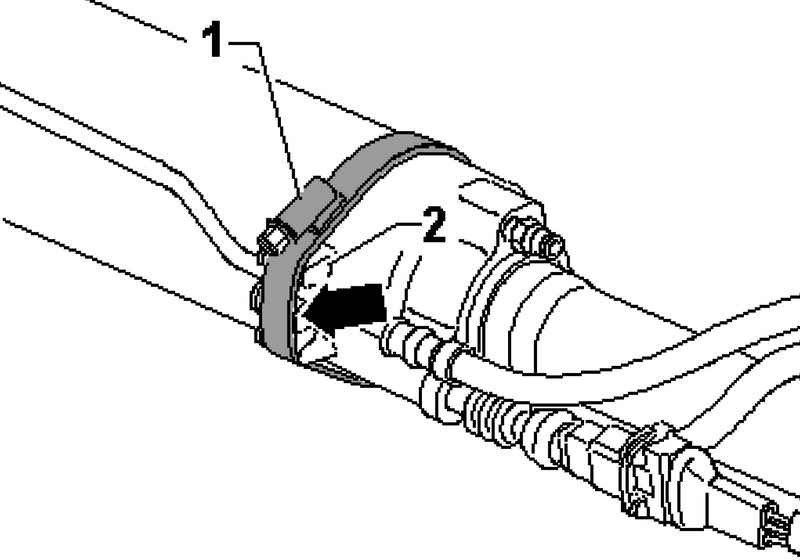
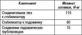
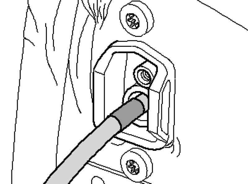
Mounting position clamps hydraulic lines to the disconnects stabilizer Lock clamp 1 should be on the holder 2. Thus, tightening the clamp from below.
| Fig. 4.60. Mounting position clamps hydraulic lines to the disconnects stabilizer
|
Removing the interrupted stabilizer Turn the hydraulic system depressurised mode.
ATTENTION Switchable stabilizers before starting work to include. Otherwise inadvertent inclusion of stabilizers can lead to injury. |
Remove the bottom screen proofing.
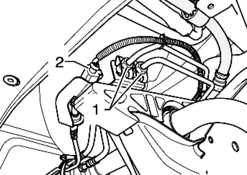
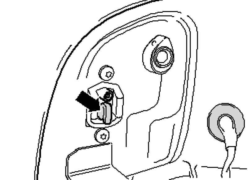
Disconnect both hydraulic lines and electrical connections 1 2 (Fig. 4.54). When installing the pipes are not to be confused. Check whether there is a label on the front "in the direction of" the pipeline. If not, apply a new one. Loosening pipes, they hold open-end wrench.
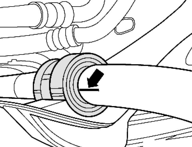
Remove collars stabilizer and mark them with the mounting position of the stabilizer bearing (Fig. 4.61). Disconnect the regulator from the connecting rod. Installing disable stabilizer. Installation is carried out in reverse order.
At the same time pay attention to the following. The labels put on the stabilizer when removed. larger outer diameter of the bearing halves should be directed outwards. After installing the hydraulic system must be bled.
Tightening torques
When tightening the hold of the hexagon nut. Install the front screen proofing.
Checking and topping up the hydraulic oil disconnected stabilizers Turn the hydraulic system using a depressurised mode. Remove the rear left lamp.
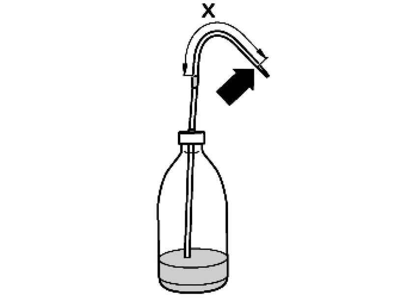
Note the size of the X. X = 135 mm.
Enter the irrigation tube to the labeling in the filler hole (Fig. 4.65). Pour oil central hydraulic power steering system and the G 000 to 002 until the pipe starts to suck oil from a plastic bottle. Thereafter evacuating by a plastic bottle of the oil tank as long as the tube begins to suck air. At the same time follow the label applied to the tube.
|