printable version printable version
Wheel bearing
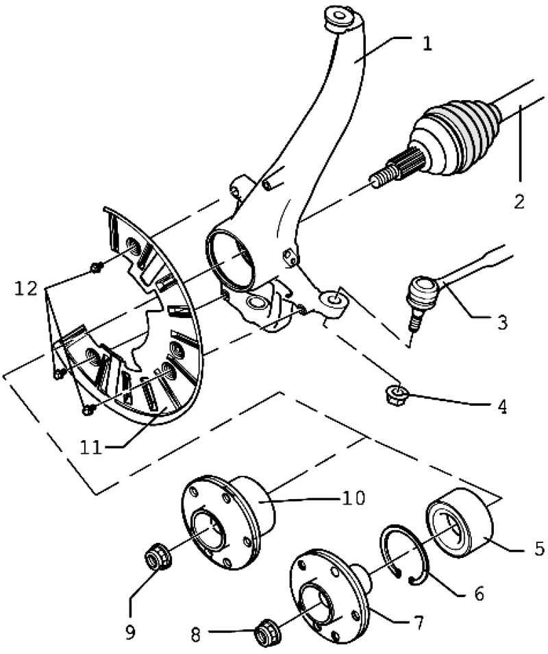
| Fig. 4.75. Components of support: 1 - wheel bearing housing; 2 - the drive shaft; 3 - wishbone; 4 - Self-locking nut; 5 - wheel bearing; 6 - a lock ring; 7 - wheel hub; 8 - Self-locking nut; 9 - Self-locking nut; 10 - wheel hub bearing; 11 - guard; 12 - hex bolt
|
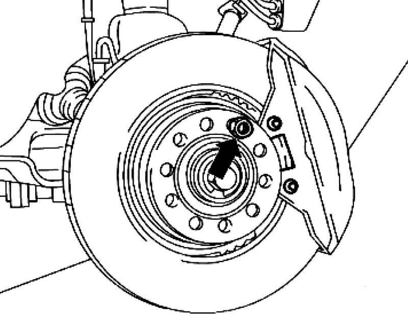
Removing the wheel hub bearing First, remove the drive shaft. Tightly screw the upper suspension arm to the wheel bearing housing.
Remove the caliper and hang on a wire to the body. Remove the brake disc and plate. Rasklipsuyte wire speed sensor. Remove the speed sensor system ABS. Screw clamps T10205 / 12 with wheel bolts to the hub of the wheel.
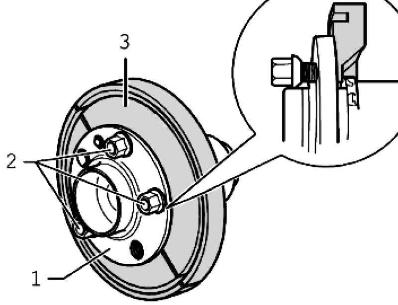
| Fig. 4.77. Installation scheme for wheel bolts
|
2 Wheel bolts must not protrude on the back side of the grip (Fig. 4.77). Install tools, as shown in Figure 4.78.
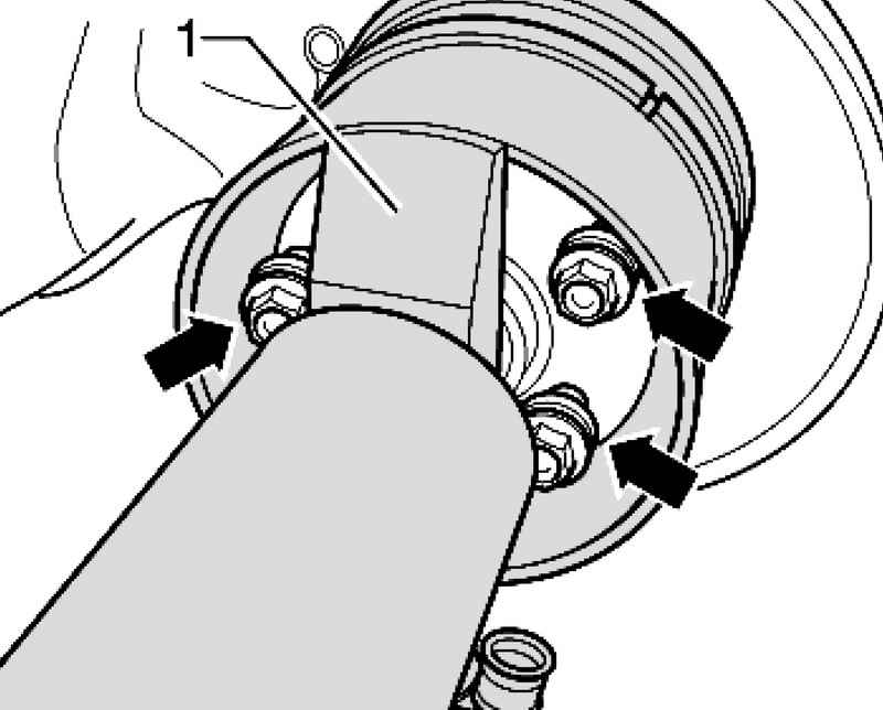
Install the wheel bolts, as shown in Figure 4.79. The wheel bolts must be visible near the bridge 1. Pull the wheel hub bearing, with the grip device.
Pressing wheel bearing Install the tools as shown in the figure.
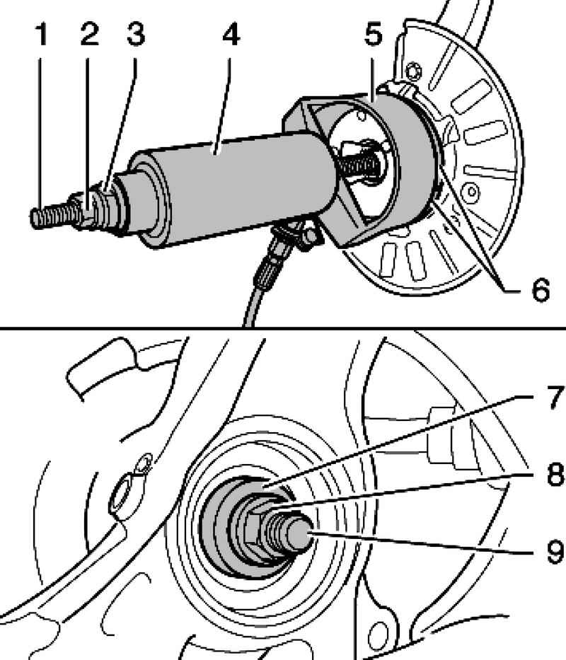
| Fig. 4.78. Install special tools: 1 - M20 threaded rod; 2 - a nut M20; 3 - push the head; 4 - hydraulic cylinder; 5 - cup; 6 - clamps; 7 - push cracker; 8 - a nut M20; 9 - Threaded rod M20
|
Connect the manifold gauge VAS 6179/1 between the hydraulic cylinder VAS 6178 and VAS 6178 cylinder pipe (Fig. 4.78). The pressures specified below refer only to the cylinder VAS 6178. Before the completion of the process of pressing the pressure gauge should show a pressure in the range from 90 to 140 bar. The maximum pressure of the pressing should not exceed 310 bar. Drive wheel hub until it stops. Clean the drive shaft splines. Set the drive shaft Further installation in reverse order.
|