printable version printable version
Pumping of fuel from the tank
The order of execution of works Open the fuel filler hatch.
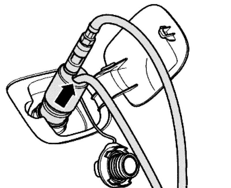
| Fig. 2.311. Installation devices for pumping fuel from the tank
|
Insert the bilge hose (Fig. 2.311) device for pumping fuel VAS 5190 by about 170-180 cm in the neck of the fuel tank and pump out the fuel.
NOTE If the fuel is no longer pumped, the fuel tank is drained so that the flange of the sensor can be safely opened. With the remnants of the fuel tank can be removed. |
If you want to work on the fuel pump and sensor, do the following:
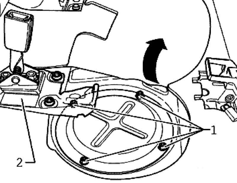
Cut the carpet from the point A to point B in the pre-notched site (Fig. 2.309). Remove the nuts securing the cover 1. If necessary, remove the armrest support bracket 2 or the support bracket. By the connection for fuel supply and fuel auxiliary heater enclose rags and disconnect the hose.
NOTE To do this, click on the coupling. |
Disconnect the connector of the fuel pump and the fuel level sensor.
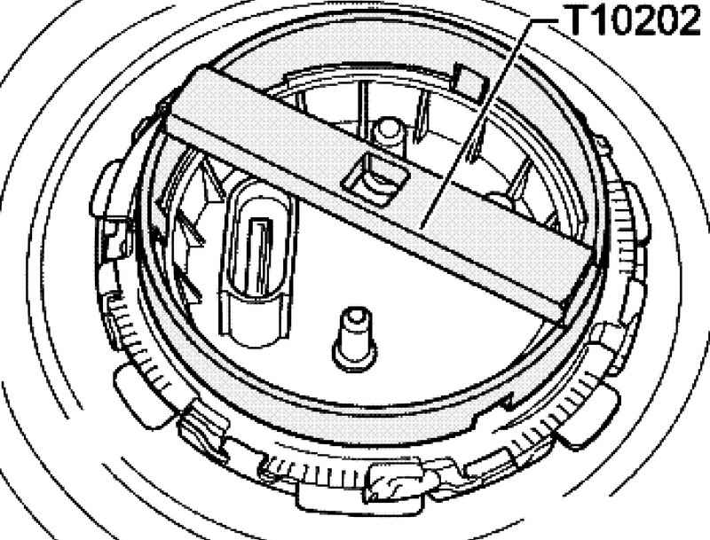
Remove the snap ring with a wrench T10202 from the flange of the sensor (Fig. 2.312). Gently lift the sensor flange. Insert the bilge hose device for pumping fuel VAS 5190 as far as possible to the right and left sides of the fuel tank and pump out the fuel. When working on the left side of the tank, follow the guidelines above.
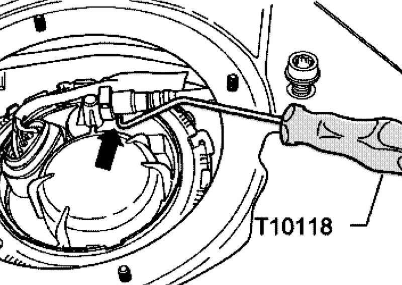
When disconnecting the vent tube hose couplings button they can not be pressed. At the same time, use the assembly tool T10118 (Fig. 2.313). In further work with the internal parts of the fuel tank sensor flange may be removed. If it was only necessary to drain the fuel from the tank, it should re-install the sensor flange. Before installation, check the O-rings in the flanges are tight.
NOTE If the O-rings were swollen due to the impact of fuel, they must be replaced. |
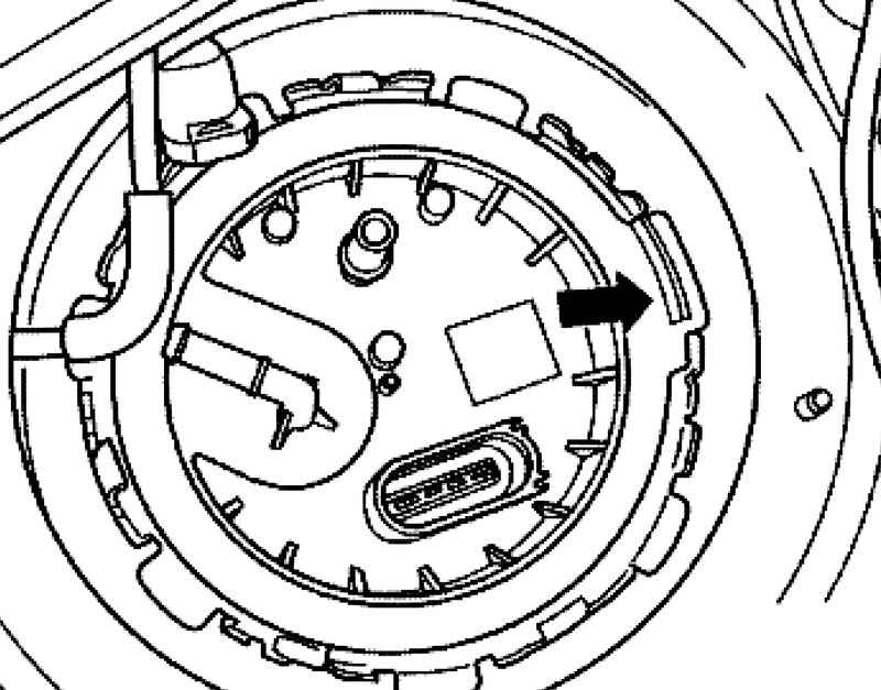
| Fig. 2.314. The direction of the installation flanges
|
Install the sensor flange with the locking plate in the direction of movement (Fig. 2.314). Screw circlips right and left by a torque wrench T10202 145 Nm.
|