printable version printable version
Instructions for chains
Schemes of large complex systems are divided into separate parts of the circuit. This is designated as 1 (3) 2 (3), etc. Battery (1/1), the ignition switch (3/1) and the central electric unit of the passenger compartment (11B) are always at the top of the circuit. Connectors central electric unit (J1, J14, etc.) are given in the list of connectors, see "slots".
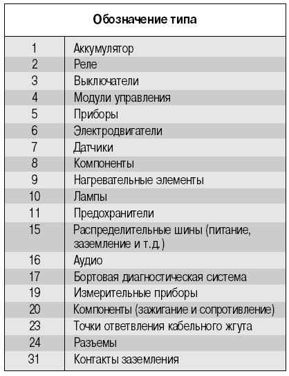
| Fig. 10.87. Symbols used in diagrams
|
| Fig. 10.87. Symbols used in diagrams
|
Fuse. Fuses are distributed between the central electric unit. Legend of the engine compartment fuse always start with 11A. Legend of the passenger compartment fuse begins with 11B. The engine compartment is also installed more powerful fuse. The diagrams are highlighted in bold lines. Table. Some circuit breakers are provided tables (for example, the ignition switch), which shows which contacts are electrically connected to each other at different positions of the switch. Link. A reference to a component that is not directly related to this chain. Point branch. It is a branch of the cable harness, see "Points of branches." The control module. All control modules are shown in gray. With reference to the control module unit as depicted in gray. Connector. Connector with pin numbers (component with the designation 24 / always connector). Component. Each component has its own part number. At the end of the book there is a folded sheet with a list of components. The grounding pin. Designation of contact 31 / 1-2 indicates that two connection terminal connected to the engine compartment with each other. All components of the engine compartment connected to this contact, see "grounding". It's easy to confuse the grounding 31/5 and 31/6. For some ground pins are shown various embodiments. General information, see "grounding". The types of engines: Gasoline engines -V4164S, V4184S and V4204S; turbodiesel - D4192T; turbocharged petrol engine - V4194T. Type designation. The first part of the component number indicating its type (motor, switch, etc.).
|