printable version printable version
Removal and installation of thumb pump, 5-cyl. diesel engine
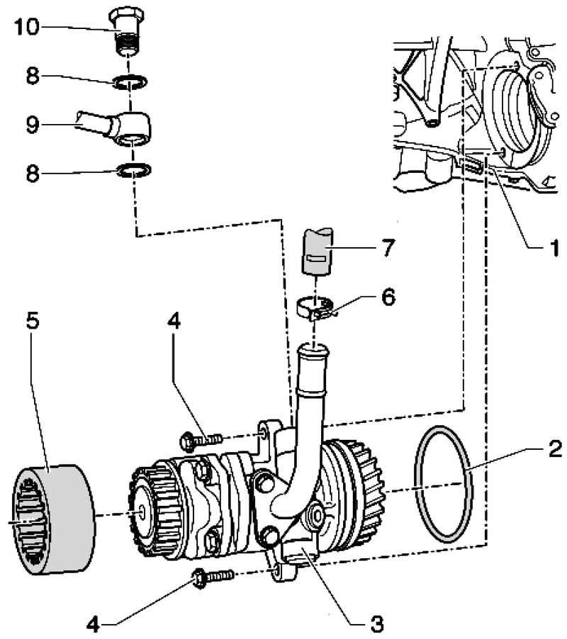
| Fig. 5.21. Components vane pump 1 - the block of cylinders; 2 - O-ring; 3 - vane pump; 4 - a bolt; 5 - coupling; 6 - a spring collar; 7 - suction hose; 8 - the sealing ring 16h22; 9 - penstock; 10 - a hollow bolt 35 Nm
|
NOTE Replace O-rings. Drain the oil no longer use.
|
Withdrawal Remove the soundproofing screen engine Remove the connecting hose intercooler Remove the left wheel arch liner
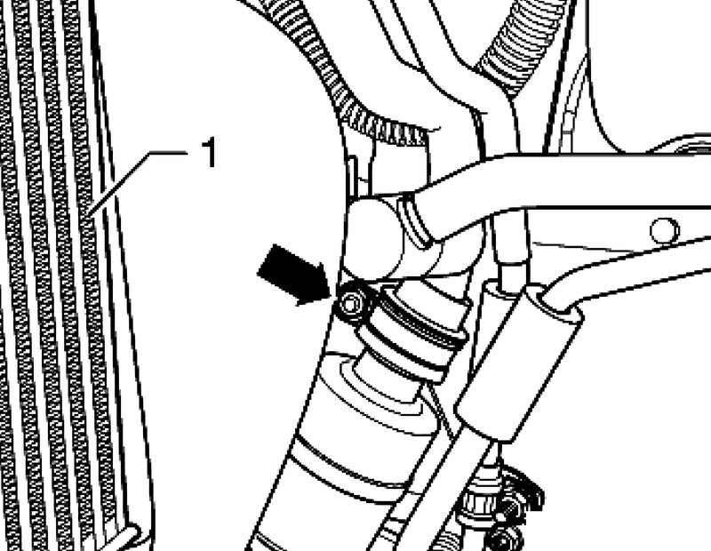
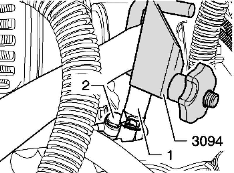
Unscrew the nut of the clamp around the pipe conditioner intercooler 1 (Fig. 5.22). Remove the air filter
Remove air conditioning compressor and set aside.
Remove banjo bolt 2. Close polyethylene pressure pipe or the like Open the spring clamp and remove the suction hose from the vane pump 1.
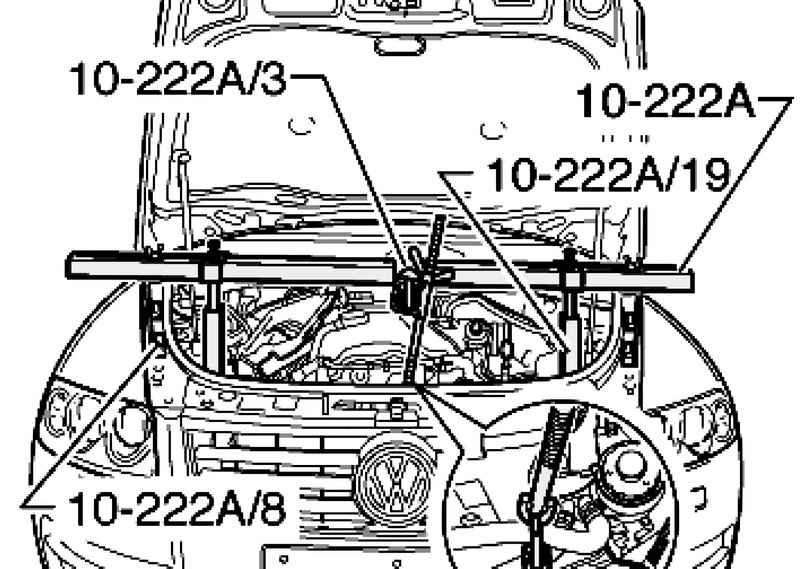
Install the console support for the engine with adapters 10-222 A 10-222 A / 3, 10-222 A / 8 and 10-222 A / 19 (Fig. 5.26). Install adapters 10-222 A / 19 on the side members. Take care not to damage the piping when installing the air conditioner 1 adapter.
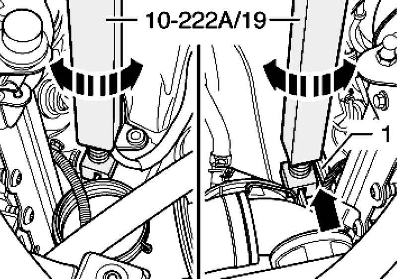
Rotate the adapter as long as they do not take the load of the machine and will not be unloaded left engine mount (Fig. 5.27). Adapters 10-222 A / 8 serve only to prevent tipping. Disconnect the connector at the motor bracket.
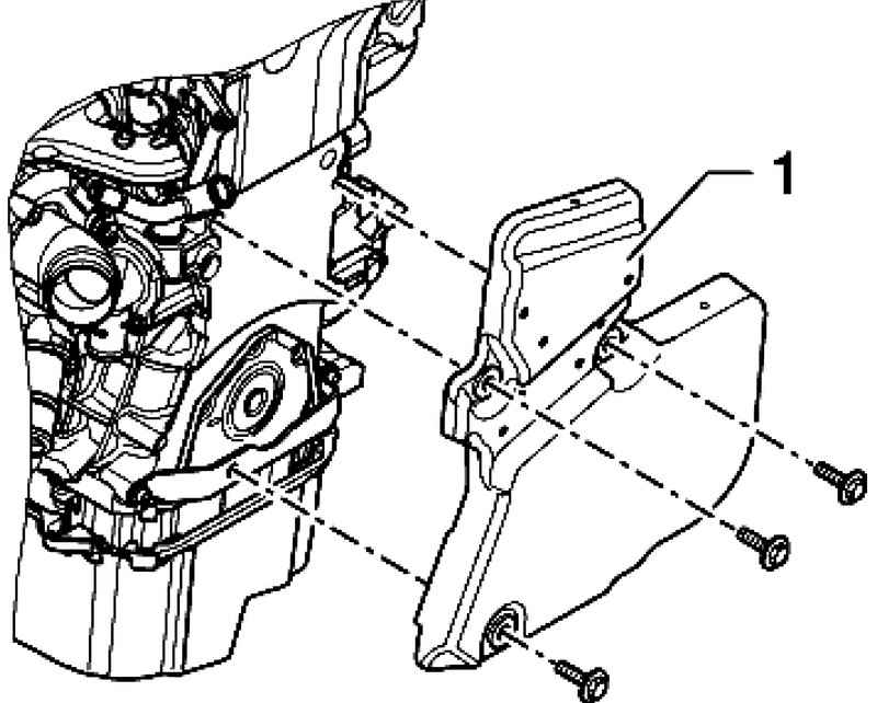
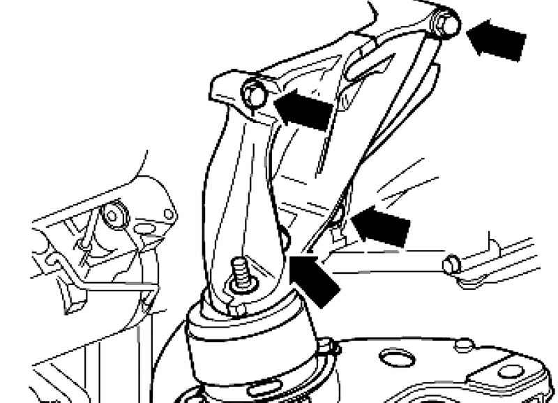
Remove the bracket bolts of the engine and remove the bracket (Fig. 5.28).
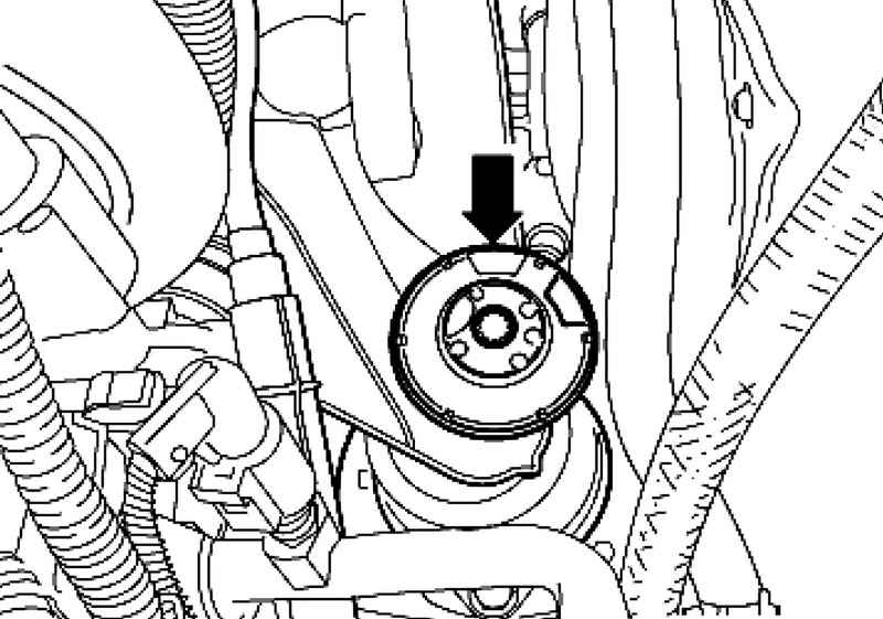
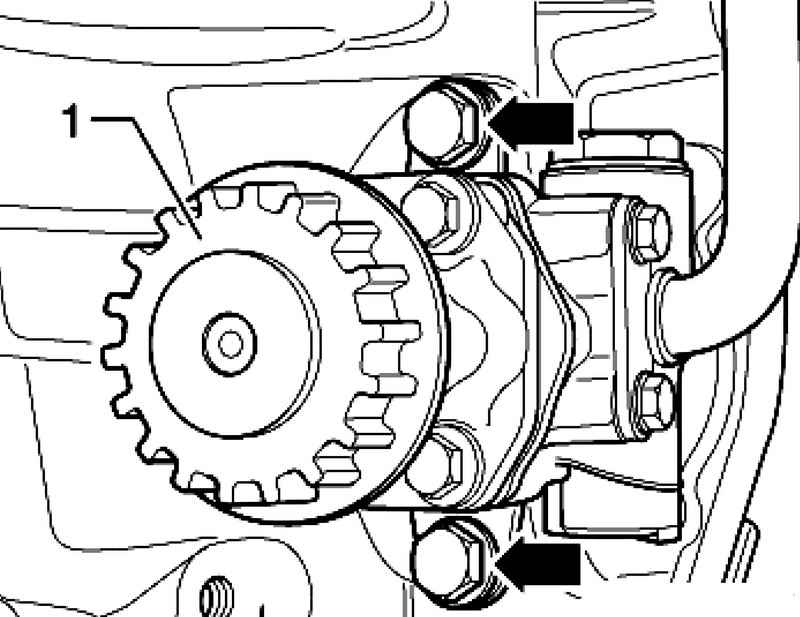
Unscrew the bolts and remove the vane pump 1 of the cylinder (Fig. 5.29).
Setting Install in reverse order, with the following should be considered. Fill vane pump hydraulic oil. Oil is filled through the suction nozzle vane pump. Rotate the hub by hand as long as oil does not come out on the discharge side. Install the vane pump. Bleed the steering system. Check the level of the hydraulic oil. system. Check steering system for leaks.
Tightening torques Vane pump cylinder block - 40 Nm + 90 ?°. Banjo bolt to vane pumps - 35 Nm. Bracket engine cylinder block - 55 Nm. The damper to the bracket / engine support - 75 Nm.
|