printable version printable version
Removal and installation of thumb pump, 6-cyl. diesel engine
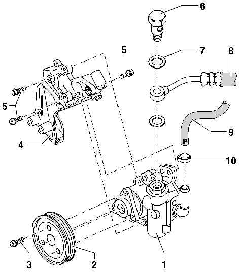
| Fig. 5.30. Components vane pump: 1 - vane pump; 2 - pulley; 3 - Allen screw; 4 - the holder; 5 - Allen screw; 6 - a hollow bolt; 7 - O-rings 16 x 22; 8 - pressure hose; 9 - suction hose; 10 - a spring collar
|
NOTE Replace O-rings. Drain the oil no longer use. Oil for hydraulic systems. Parts number G 002000. |
Withdrawal Allow space for access to all the moving and hot components.
ATTENTION When all installation work, in particular in the engine compartment, because of the tight layout, consider the following. Lines of all kinds, such as fuel and hydraulic system reservoir with activated carbon, cooling systems, the coolant pipes under negative pressure, and electric lines must be laid so that they were originally laid. |
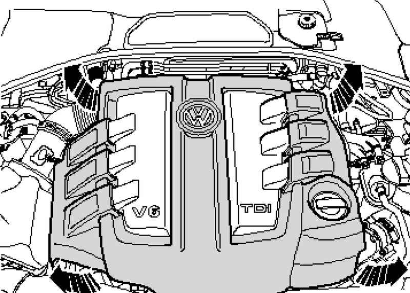
Carefully remove the decorative cover with 4 locking bolts (Fig. 5.31). Mark the direction of rotation V-belt. Remove the serpentine belt.
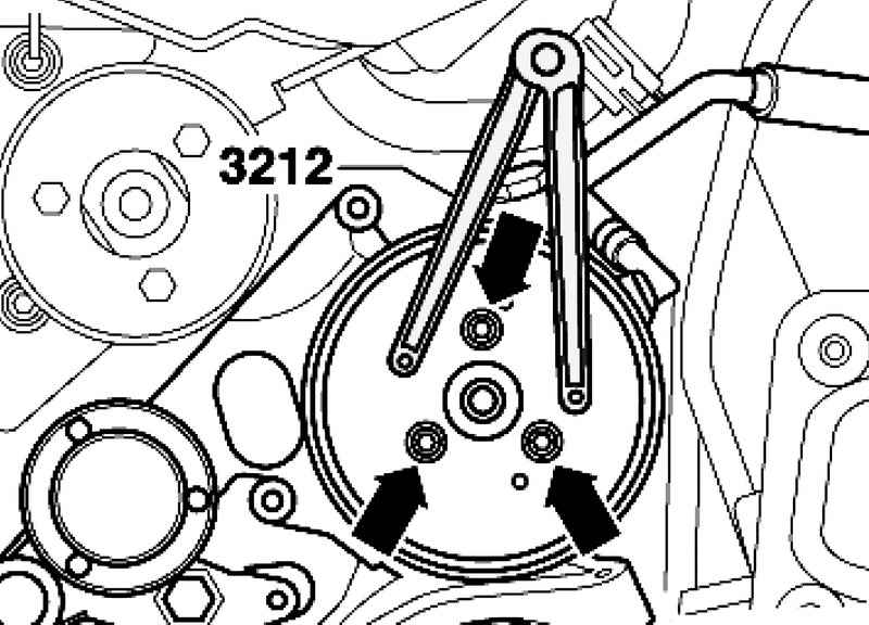
Unscrew the screws while holding the pulley V-belt using the trunnion key 3212 (Fig. 5.32). Clamp suction pipe using hose clamps up to 25 mm and remove vane pump. Remove the banjo bolt.
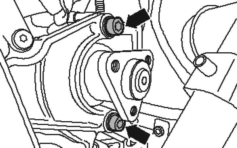
Unscrew the bolts and remove the pump from the wing attachment (Fig. 5.33).
Setting Install in reverse order, with the following should be considered. Fill vane pump hydraulic oil. Oil is filled through the suction nozzle vane pump. Rotate the hub by hand as long as oil does not come out on the discharge side. Install the vane pump in place, with the first tighten front bolts.
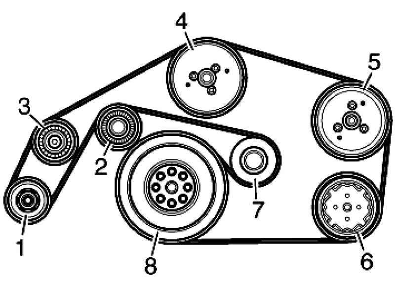
| Fig. 5.34. Contour V-ribbed belt (atomobili with a 6-cylinder diesel engine): 1 - a pulley belt transmission - three-phase generator; 2 - discharge roller; 3 - the discharge roller; 4 - a pulley belt transmission - the coolant pump; 5 - a pulley belt transmission - vane pump Power Steering; 6 - a pulley belt transmission - air-conditioning compressor; 7 - a tension roller; 8 - a pulley belt transmission - crankshaft
|
Install poly V-belt and check the belt pulley on the bias (Fig. 5.34).
NOTE When installing the V-ribbed belt watch over the correctness of its landing in the pulleys. |
Bleed the steering system. Check the oil level. hydraulic system and top up if necessary. Check steering system for leaks.
Tightening torques V-belt pulley transmission vane pumps - 25 Nm. Banjo bolt to vane pumps - 35 Nm. Vane pump to the mount - 25 Nm.
Note Use new O-rings.
|