printable version printable version
General information on the injection system
Fuel hoses in the engine compartment are allowed to fix only the spring clamps. Using clamps and clamps with screw fastening is not allowed.
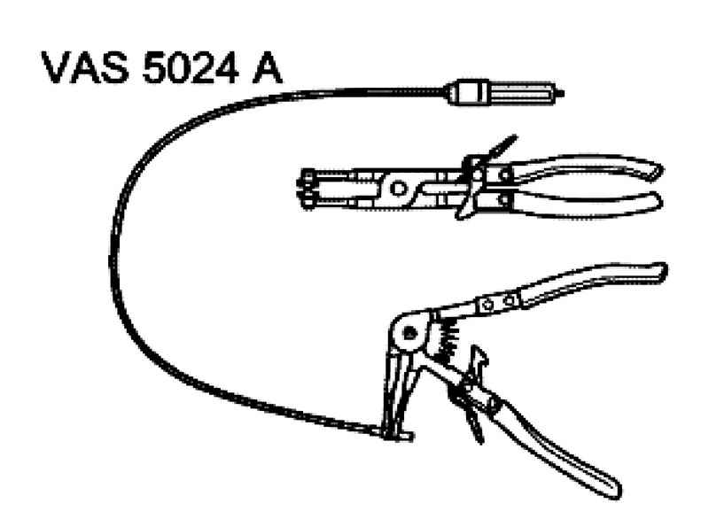
For the installation of spring clamps recommended use pliers for spring clamps VAS 5024 A or VAG 1921 pliers (Fig. 2.270). To maintain perfect operation of electrical components required voltage is less than 11.5 V. Do not use sealants containing silicone. Remains silicone sucked engine does not burn through and damage the Lambda probe.
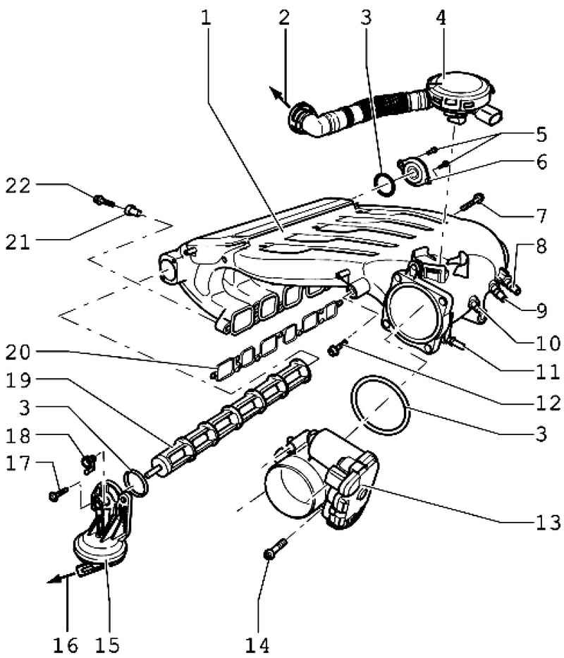
| Fig. 2.271. Details of the intake manifold 1 - intake manifold; 2 - to the cylinder head cover; 3 - O-ring; 4 - valve crankcase ventilation; 5 - a bolt 10 Nm; 6 - a cover of the bearing; 7 - a bolt 20 Nm; 8 - the vacuum nozzle; 9 - the vacuum union (in vehicles with Engine code AZZ, BKJ, BMV, and BRJ closed plug); 10 - the vacuum nozzle; 11 - the vacuum nozzle; 12 - a bolt 20 Nm; 13 - Throttle Control Module J338; 14 - bolt 10 Nm; 15 - the vacuum actuator; 16 - a step change in the geometry of the valve inlet N156; 17 - bolt 10 Nm; 18 - setting lever; 19 - pin cylinder; 20 - a lining; 21 --fitting sleeves; 22 - a bolt 13 Nm
|
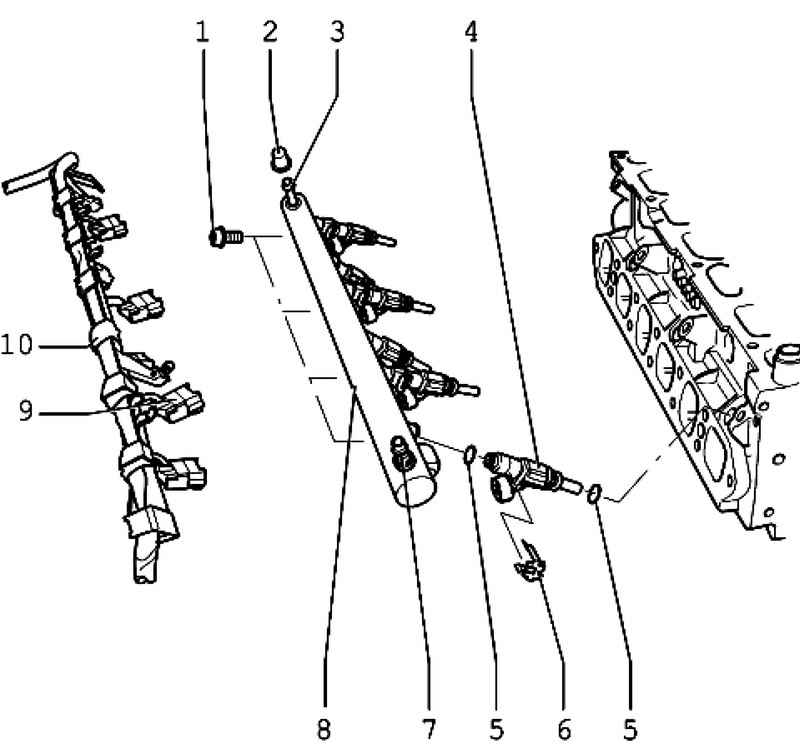
| Fig. 2.272. Details of the fuel rail: 1 - a bolt 10 Nm; 2 - a protective cap; 3 - air vent; 4 - 6 cylinder injector N84; 5 - O-ring; 6 - mounting bracket; 7 - coupling, fuel supply; 8 - Fuel rail; 9 - plug; 10 - harness
|
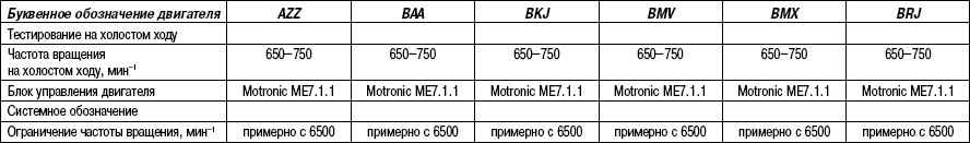
Technical characteristics of the injection petrol engines
Disabling the pipeline compressor air suspension
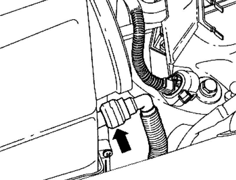
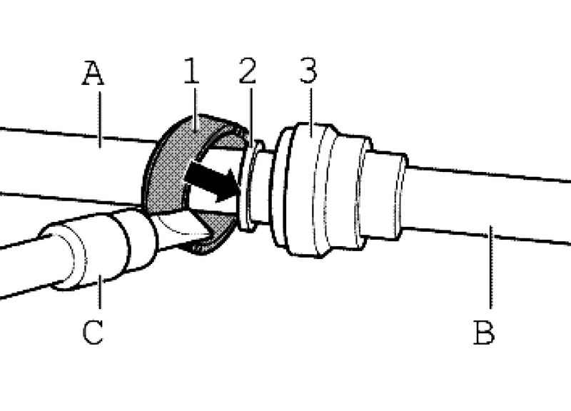
| Fig. 2.273. Connection pipe with filter vozduschnym
|
Disconnect the pipe from the air filter (Fig. 2.273) as follows. Gently pry the lock ring 1 green screwdriver. Then push down on the clamp ring 2 in the direction (Fig. 2.273).
Then unplug the weakened pipe in pipe A from the air filter (Fig. 2.274).
security measures For security purposes, prior to depressurization of the system power supply, remove the fuses 13 and 14 of the fuse holder, as the fuel pumps can be activated when triggered driver door contact switch. Fuses 13 and 14 are located in the fuse box in the electronics box, the left side of the plenum chamber.
ATTENTION The fuel is pressurized. Before depressurization of the fuel system, connect a pumping device VAS 5226 and relieve the pressure. |
To avoid personal injury and / or damage to the injection system and the ignition must observe the following requirements. Disconnecting and connecting electric cables of the injection and ignition, as well as measuring devices is only allowed with the ignition off. Do not touch or disconnect the high voltage wires with the engine running and with the start-up speed. When using the instrumentation during the test drive, observe the following rules. Control and measuring devices must be firmly secured in the back seat. There you should be working with them a second specialist. When working with instrumentation specialist will be on the front passenger seat, the airbag is triggered it can get injured. If the engine is supposed to trigger a scroll speed, do not have it, disconnect the plugs of the ignition coils 1..6.
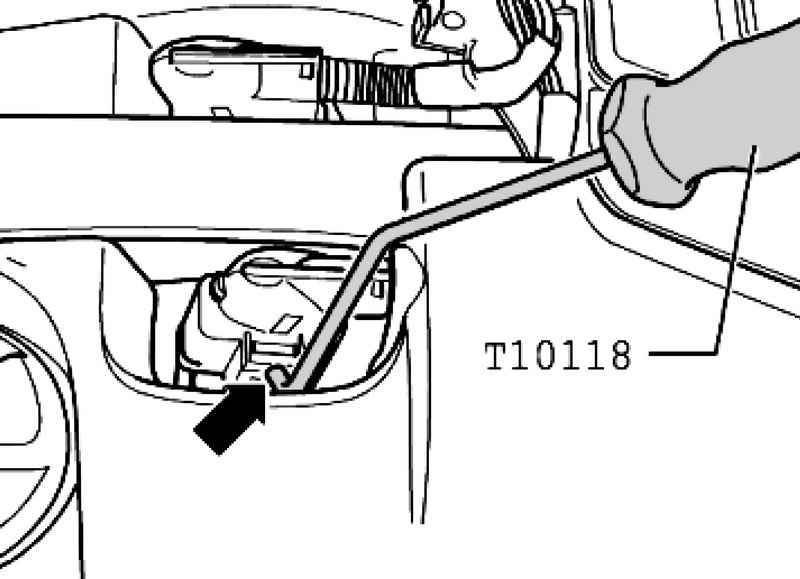
To do this pry tool T10118 for mounting clamp and carefully remove the plug (Fig. 2.275).
|