printable version printable version
Removing the front of the main transfer
Unscrew the wheel bolts. Raise the vehicle. Remove the front wheels. Remove the front left and right wheel arch liners.
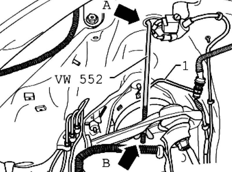
If cars are installed pneumatic shock absorbers, you must unplug the duct 1 and let the air (Fig. 3.144). Then tighten the connection to the specified torque. Establish a spring fixture VW 552 on both sides of the car into the top hole in the wheel arch and the upper suspension arm. Lightly squeeze the lever, so as not to damage the ball pin of the hinge suspension. Remove noise insulation below engine / gearbox. In the presence of - remove the underbody protection at the front of the main transmission. Remove the holder soundproofing.
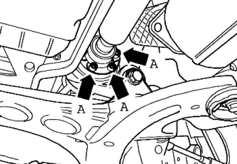
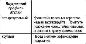
| Fig. 3.130. Fixing bolts of the front propeller shaft
|
Separate and secure the front propeller shaft front final drive A (Fig. 3.130). Remove the left and right drive shafts. If necessary - use the nozzle for loosening bolts T10099 / 1.
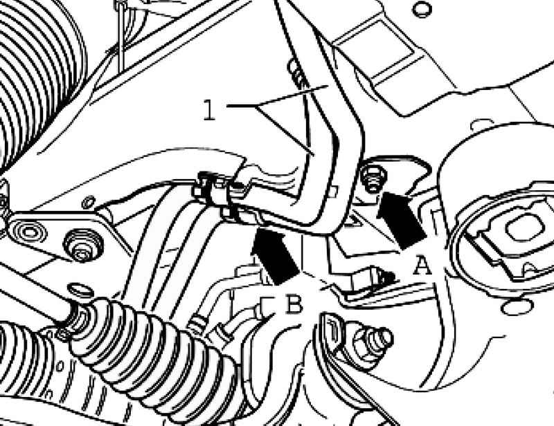
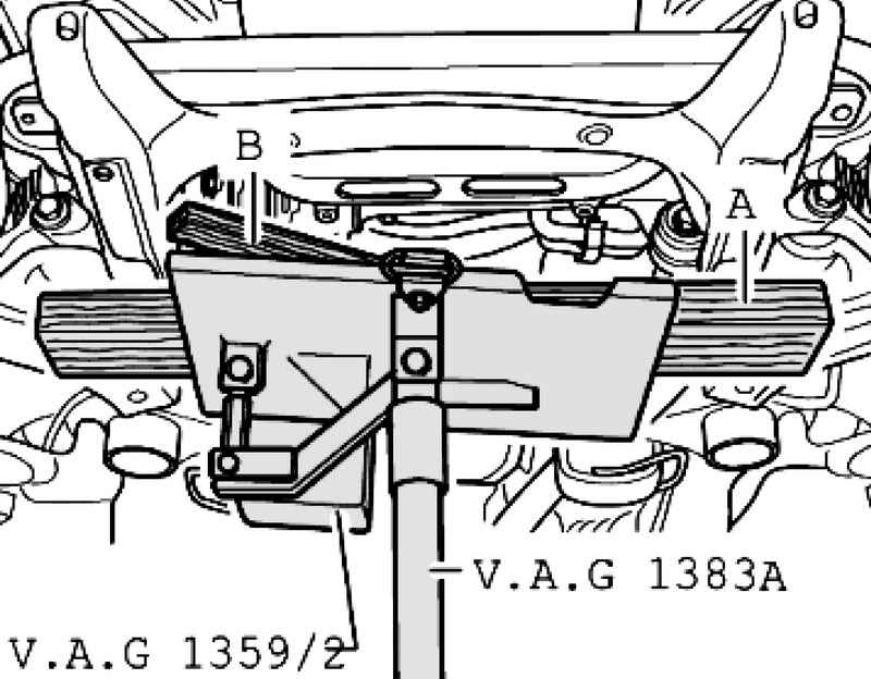
If there - clear the screen A with the steering mechanism (2 screws) (Fig. 3.145). Remove the bolt in the universal joint of the steering mechanism and remove the joint from the steering mechanism.
If necessary - remove the tube cooling system 1 from the left side member. For this Okrut nut and holder (Fig. 3.146).
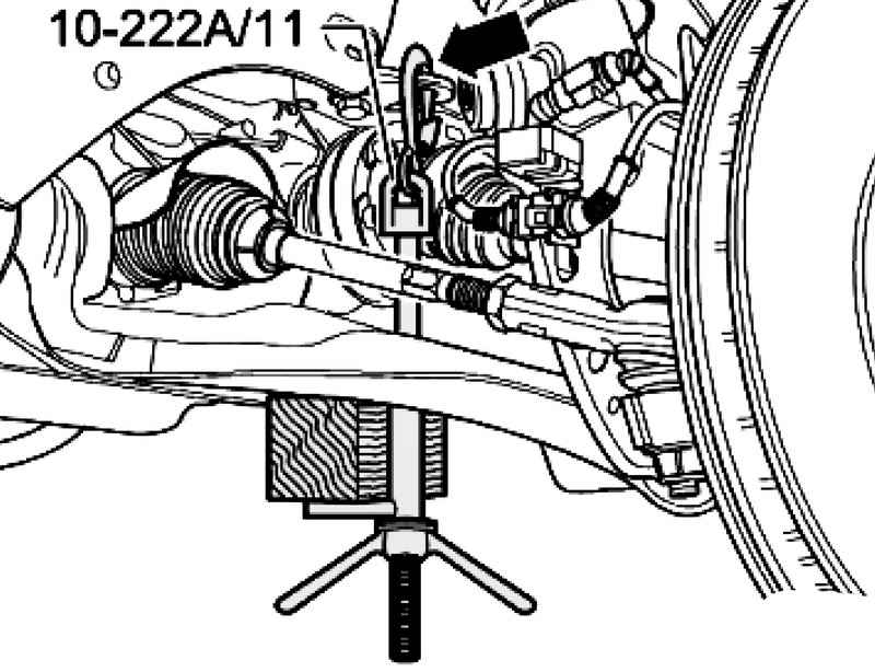
Insert axis 10-222 A / 11 in the hinge bracket motor for the right and left sides (Fig. 3.147).
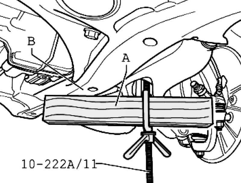
Insert a piece of wood A length of about 300 mm bracket axles 10-222 A / 11 (Fig. 3.148). This bracket should be sent back. Tighten the clamp axes, for that wooden bars should lean into the bracket mounted units B. Place the tip of Jacks in the rack for the engine and gearbox VAG 1383 A.
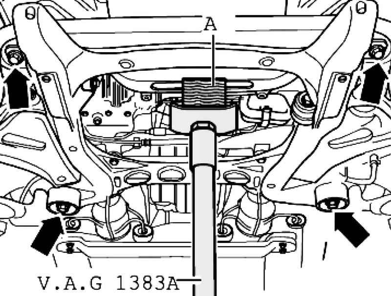
Set the rack for the engine and gearbox VAG 1383 A under the engine bracket and press gently (Fig. 3.149). Remove the mounting bracket bolts mounted units
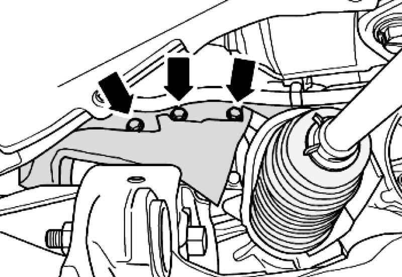
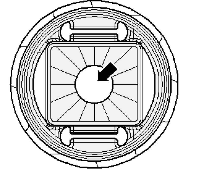
| Fig. 3.150. Place inspection of the internal profile
|
Check the internal profile of the rubber bushing in the support (Fig. 3.150).
Remove the mounting bracket bolts mounted units to the body.
Remove the connecting rod to the left and right stabilizer from 1 (Fig. 3.151). Unscrew the screw connection of pneumatic or standard shock absorbers at the bottom of the suspension arm. It is necessary to lower the bracket mounted units through the axis of 10-222 A / 11, about 50 mm in the direction of the arrow to remove the two bolts. Use these bolts 2 with additional washers or bolts M 14x1,5 length of about 90 mm to fix the motor bracket on left and right on the body 3. Remove the rack for the engine and gearbox VAG 1383 A from under the arm of the engine.
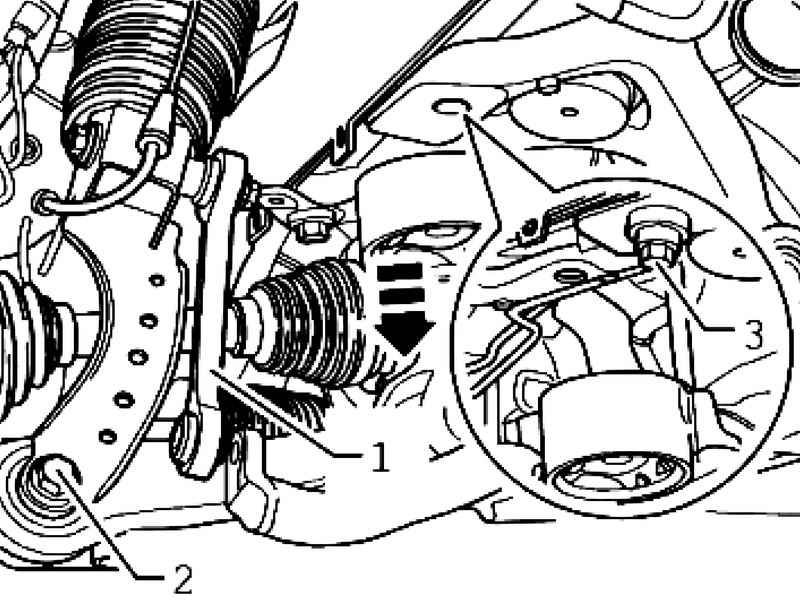
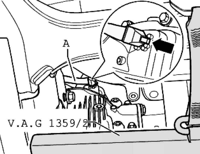
Place the rack for the engine and gearbox VAG 1383 A, with a universal focus gearbox 1359/2 under the bracket mounted units and press gently (Fig. 3.152). At the same time, place a wooden shim under the A bracket mounted units and in front of the main transfer. Fix the bracket mounted units using universal belt stop for gearbox VAG 1359/2. Remove the axis of 10-222 A / 11 from the bracket mounted units.
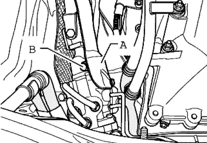
Carefully remove the vent pipe nipple A with the front of the main transfer (Fig. 3.153).
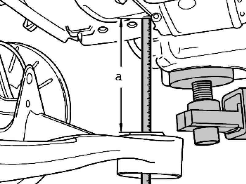
Carefully lower the bracket mounted units from the front main gear on the value of A (about 200 mm) (Fig. 3.154). Measure the A between the body and the contact surface of the bracket mounted units.
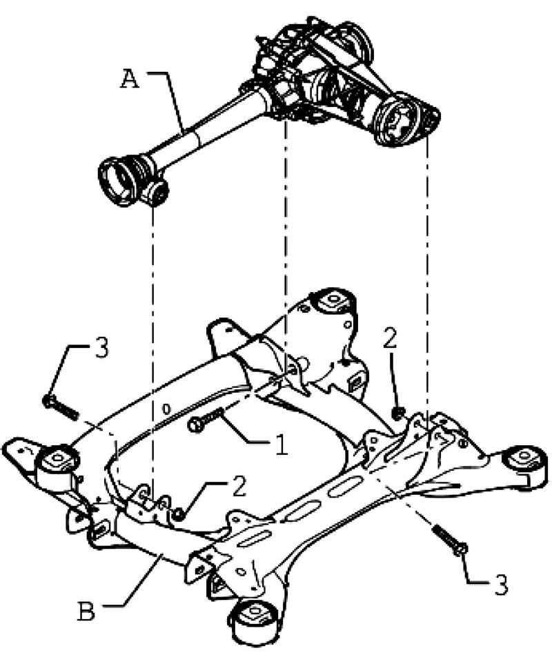
| Fig. 3.155. Bolts and nuts on the front of the main transfer arm mounted units
|
Remove the connecting bolts and nuts 1-3 front final drive A bracket mounted units B (Fig. 3.155). To remove the front of the main transfer needs assistant.
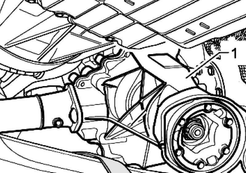
| Fig. 3.156. Removing the front of the main transfer
|
Remove the front main transmission 1 between the bracket mounted units and the motor / gearbox down as follows (Fig. 3.156). First, lift the left driveshaft. Then remove with a second mechanic front of the main transmission mounts bracket mounted units. At the same time, remove the right propeller shaft of the shaft flange. Lift the front of the main gear steering and bring back. Installation of the front of the main transfer Install in reverse order, with the following should be considered. Always replace the mounting bolts of the front propeller shaft. To install the front main transmission mount bracket mounted units need a second mechanic. Install the connecting bolts and nuts 1-3 front final drive A bracket mounted units B (Fig. 3.155). Lift the bracket mounted units, with an emphasis gearbox. Carefully place the vent pipe with connection nipple A in front of the main transmission (Fig. 3.153). This pin must be horizontal and located between elevations on the body. Insert axis 10-222 A / 11 in the hinge bracket motor for the right and left sides (Fig. 3.147). Place a piece of wood measuring about 300 mm bracket axles 10-222 A / 11 (Fig. 3.148). This bracket should be sent back. Tighten the clamp axes, for that wooden bars should lean into the bracket mounted units B. Remove the rack for the engine and gearbox VAG 1383 A from under the bracket mounted units. Place the tip of Jacks in the rack for the engine and gearbox VAG 1383 A. Set the rack for the engine and gearbox VAG 1383 A under the engine bracket and press gently (Fig. 3.149). Pre-established, remove the screws 3 on left and right engine bracket (Fig. 3.151). Install screws 2 pneumatic or standard shock absorbers at the bottom of the steering lever. Screw the connecting rod right and left 1 to the stabilizer. Before screwing the bracket mounted units check the internal profile of the rubber bushing support (Fig. 3.150).
Tighten the sub-frame mounting. If the test was conducted of the wheels, the bolts must be replaced. Tighten bolts to torque. Remove the axis of 10-222 A / 11 from the bracket mounted units (Fig. 3.149). Install the universal joint in the steering gear and tighten the bolts in the tightening torque. If there is - to set the screen A steering mechanism (Fig. 3.145). If there is - install pipes of the cooling system on the left side member 1. To tighten the nut and the holder (Fig. 3.146). Install the front propeller shaft. Connect the drive shafts and shafts with a flange. Remove the fixture VW 552. Remove the front left and right wheel arch liners. Check the oil level in front of the main transmission If there is - install underbody protection at the front of the main transmission. Install the front wheels. If necessary - after the installation, check the level of the installation angles of the wheels.
|