printable version printable version
Removal, installation and tension of the toothed timing belt
Withdrawal
ATTENTION When all installation work, in particular in the engine compartment due to the tight layout, consider the following: the line of all kinds (such as fuel, hydraulic absorber, activated carbon, cooling system, coolant, brake lines, vacuum hoses), and and electrical wires must be routed as they were originally laid. Provide sufficient space to all moving or hot components to avoid damage to any kind of lines. |
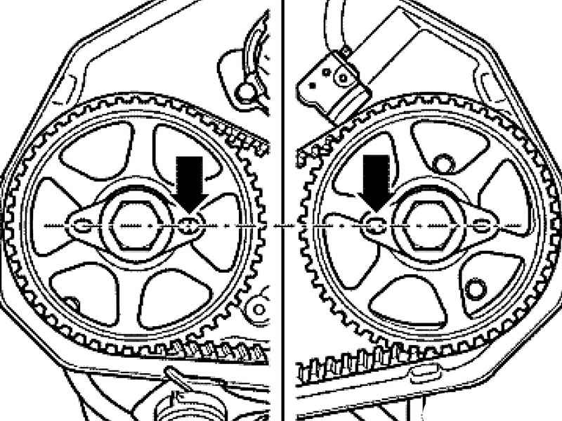
Remove the soundproofing screen. Remove the fan bracket with the fan cooling system. Result a radiator framework in service position. Mark direction of travel V-ribbed belt and remove it. Remove the right and left cover of a gear belt. Mark the water-resistant felt-tip direction of rotation on a gear belt. Bring the crankshaft to top dead center. The mark on the cover of the toothed belt A must coincide with the notch on the belt pulley B.
| Fig. 2.106. The combination of the holes in the mounting plate
|
Check the position of the camshaft gears. Large holes in the mounting plate (Fig. 2.106) must be located opposite each other on the inner side.
NOTE If larger openings are located on the outer side of the gear must rotate the crankshaft has one turn in the direction of rotation. |
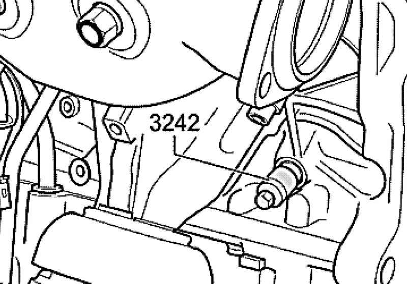
Unscrew the cap to the left of the cylinder (Fig. 2.100). Crankshaft TDC hole to be seen hole for the screw plug and feel to the touch. Gently twist the locking bolt 3242 into the hole until it stops, and thus secure the crankshaft from turning. Remove the middle cover of the toothed belt. Remove the vibration damper.
NOTE Vibration damper is secured to the crankshaft by 8 bolts. |
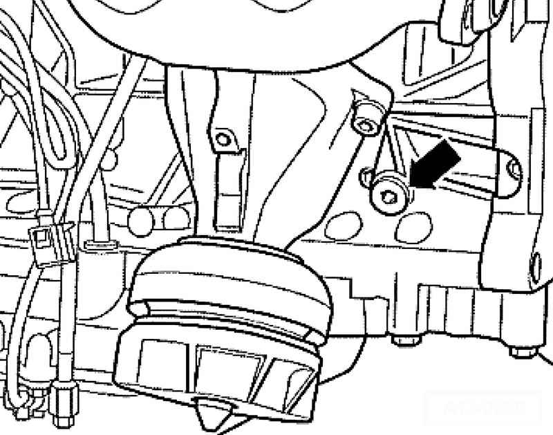
First unscrew the screw 1 from the oil filter housing, and then the cover bolts 2 toothed belt tensioner (Fig. 2.107). Remove the cover.
NOTE Toothed belt tensioner is oil fence. Therefore, it is slowly shrinking. To fix the tensioner, use the locking pin T40011. If necessary, align the holes in the housing and on the piston to tension the tensioner via thin wires or needle-nose pliers. |
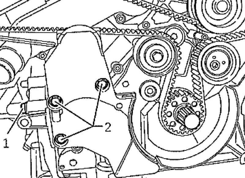
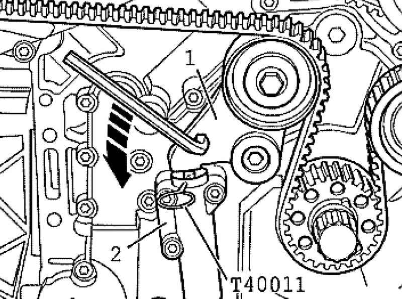
Scroll down the lever of a tension roller of a gear belt 1 hexagon socket in the direction (Fig. 2.108). Once the lever compresses tensioner 2 so that the holes in the housing and the piston are opposite each other, lock the tensioner locking pin T40011.
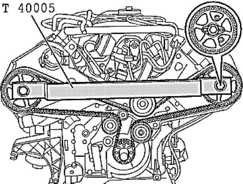
Insert camshaft clamp T4000 to the mounting plate and remove the camshaft securing bolts by turning them approximately 5 turns (Fig. 2.109). Remove clamp camshaft T40005.
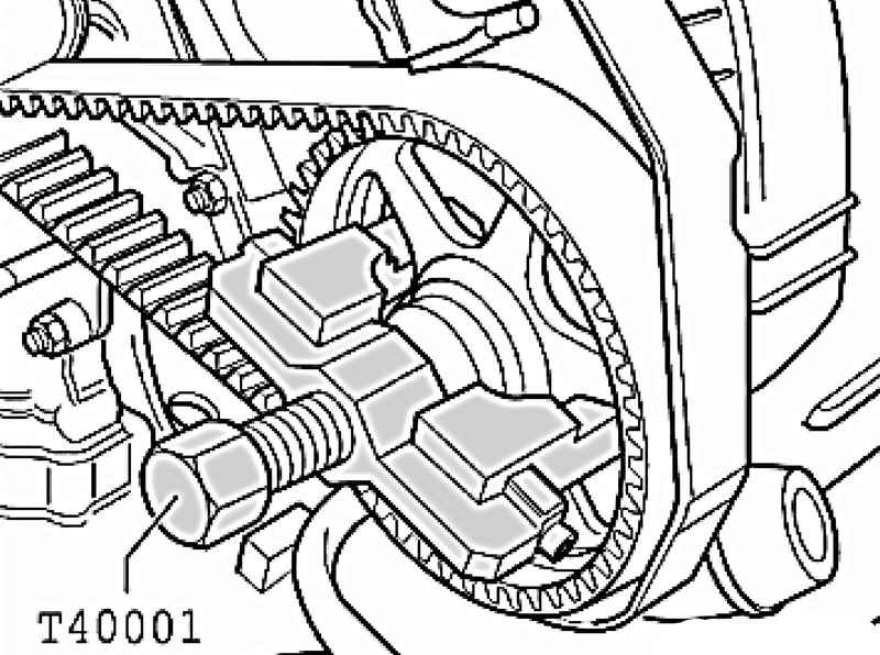
Then, using a two-handed hook puller T40001 and T40001 / 2, remove the camshaft gear with the cone (Fig. 2.110).
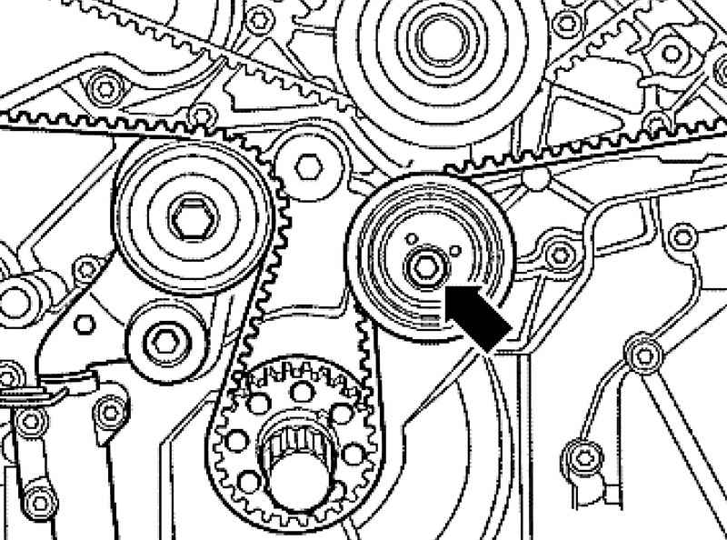
Unscrew the tension roller (see. Fig. 2.111) and remove the timing belt.
Installation and tension
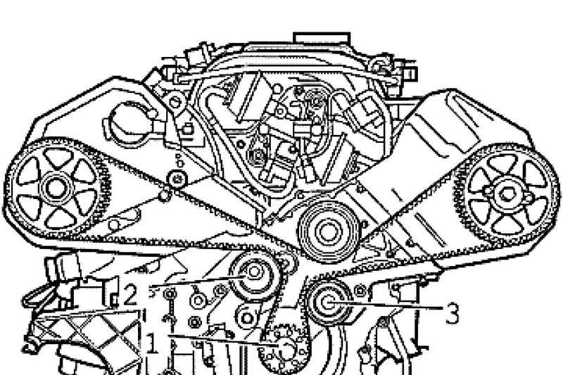
First, lay the timing belt on the crankshaft gear 1, then the slip tensioner pulley 2 and then on the tension roller 3. Further, as shown in the figure on the camshaft gear and pulley the coolant pump (Fig. 2.112).
NOTE If the belt is operated earlier, you need to pay attention to the mark on the direction of travel. |
NOTE Camshaft gears have a little scroll on cones camshafts. |
Reinstall T40005 camshaft clamp on gear.
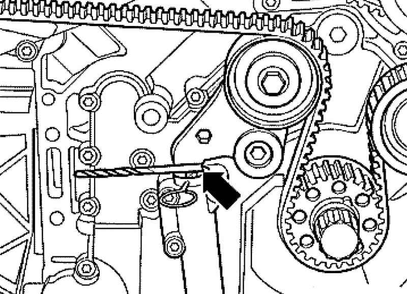
Put a 5 mm drill bit between the tensioner arm and the tensioner piston (Fig. 2.113).
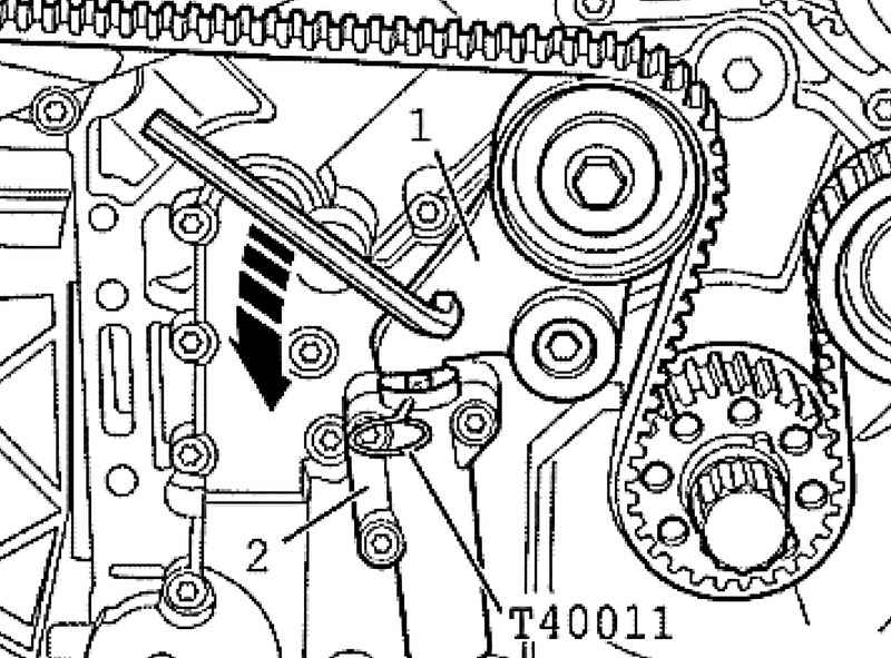
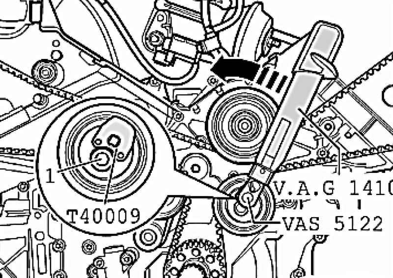
Tighten the attenuated tension roller torque wrench VAG 1410 with nasazhennoj ratchet wrench VAS 5122 and for idlers T40009 counterclockwise (Fig. 2.114) with a torque of 4 Nm. In this position, tighten the bolt 1 to 22 Nm. Then remove the 5 mm drill. Scroll down the lever of a tension roller of a gear belt 1 hexagon socket in the direction (Fig. 2.114). Once the lever to the piston will compress the timing belt tensioner 2, remove the locking pin T40011.
Turn the lever of a tension roller of a gear belt 1 hexagon socket in the direction (Fig. 2.115) and place between the body and the lever 7mm drill. Screw the camshaft gear with a torque of 55 Nm. Remove the clip camshafts - T40005. Again, remove the drill bit inserted between the housing and the tensioning lever.
Remove the locking bolt 3242 out of the hole, tighten the screw plug (Fig. 2.101) and tighten it to 30 Nm.
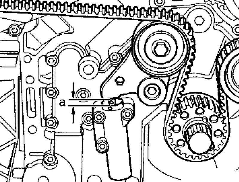
Turn crankshaft two times in the direction of rotation of the engine and check the installation size of A (Fig. 2.116). Setpoint 5 mm. Further installation is performed in reverse order.
|