printable version printable version
Anti-lock braking system (ABS)
Brake system with ABS and a dual-diagonal. Amplification is performed in a brake system with a vacuum booster. Faults affect ABS braking system and strengthening it. In the case of an ABS fault should be regarded as a change in the braking force. After ignition control lamp ABS rear wheels during braking can lock up prematurely. Vehicles with ABS Mark 25 is not equipped with a mechanical brake-power. Special software in the control unit monitors the distribution of braking force to the rear axle.
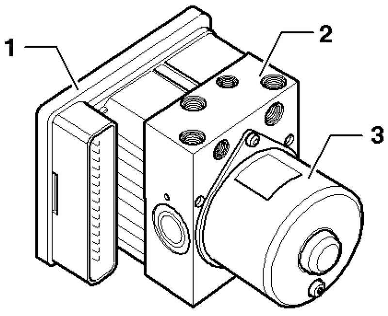
The control unit 1 and unit 2 of hydraulics form a single unit (Fig. 6.61). The separation is only possible in the removed condition. The hydraulic pump 3 can not be disconnected from the power hydraulics. New control units as spare parts are not coding. After installation you need to code them.
Electrical / electronic components
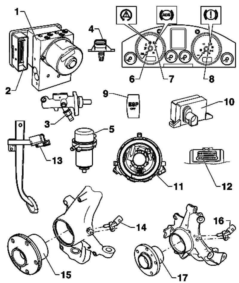
| Fig. 6.62. Electrical / electronic components: 1 - Hydraulic unit ABS; 2 - Control unit ABS; 3 - pressure sensor brake system; 4 - pressure sensor gain in the brake system; 5 - the vacuum pump the brakes; 6 - a control lamp ESP and ASR; 7 - control lamp ABS; 8 - a control lamp of brake system; 9 - key systems, ASR and ESP; 10 - sensor unit ESP; 11 - the gauge of the steering angle; 12 - diagnostic connector; 13 - brake light switch and the brake pedal sensor; 14 - front right speed sensor / front left speed sensor; 15 - wheel bearing / wheel hub assembly; 16 - rear right speed sensor / rear left speed sensor; 17 - wheel bearing / wheel hub assembly
|
Electrical / electronic components of the ABS system is shown in Fig. 6.62.
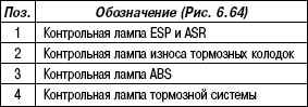
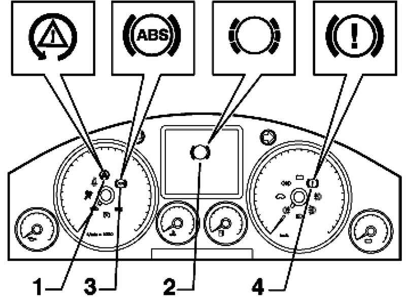
Fault warning lights If the ABS warning lamp 3 does not go out after the ignition and complete control cycle, the causes of failure can be as follows: - Voltages of less than 10; - There is a malfunction ABS.
When a defect ABS b-lock braking system is deactivated, the brake system itself remains in working condition;
- After the last start of the engine there was a temporary glitch speed sensor. In this case, the ABS warning lamp turns off automatically when you restart the engine and then a speed above 2.75 km / h; - Broken connection from the instrument cluster to the control unit ABS; - Faulty control lamp ABS.
ABS warning lamp and control lamp of brake system If the ABS warning lamp goes out and control lamp of brake lights, the cause of the fault can be as follows: - Brake fluid level is too low. When the ignition is heard three alarms. - The wiring to the brake system warning lamp K118 If you burn the ABS warning lamp 3 and the brake system warning lamp 4 - faulty ABS. In the case of an ABS fault should be regarded as a change in the braking force.
ATTENTION After ignition control lamp ABS warning lamp and brake the rear wheels can lock early when braking. |
ESP warning lamp and ASR If the ESP warning lamp and ASR does not go out after the ignition is switched on and complete control cycle, the causes of failure can be as follows: - There is a problem that concerns only the ASR / ESP. Vehicle Safety Systems ABS / EDS and EBV remain fully operational. Interrogate fault memory; - Short to positive in the button ASR / ESP; - Short to ground control control lamp ESP and ASR; - Interrupted connection from the dash to the contact 31 of the control unit ABS; - The system ASR / ESP button has been disabled ASR / ESP. If the ESP warning lamp and ASR flashes during driving, the ASR system or ESP are in control.
Brake System Warning Light If the control lamp of brake system after the ignition is not extinguished, then it may have the following reasons: - Parking brake is applied; - The switch of a control lamp of brake system is defective or incorrectly adjusted; - There is an error in the wiring. Perform electrical check. Contact the parking brake switch ABS control unit transmits information that is involved or not the parking brake. When the parking brake to regulate the ESP is a negative impact.
Control lamp of brake pad wear If the warning light brake wear does not go out after 3 sposle ignition is switched on or comes on while driving, the cause of this problem may include the following: - Brake linings may be worn. Check brake pads front and rear wheels. Replace the pads if they are worn out; - There is a fault in the wiring.
Removal and installation of components of the ABS system on front and rear axles
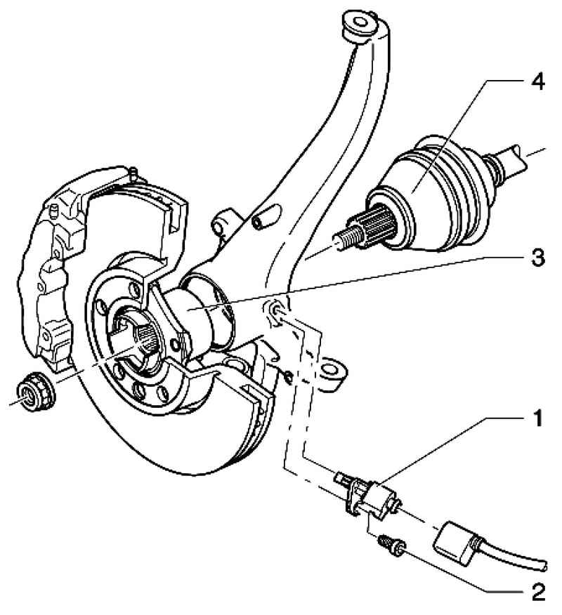
| Fig. 6.65. Components of ABS on the front axle: 1 - speed sensor ABS; 2 - a bolt with hexagon socket, 8 Nm; 3 - wheel hub bearing (bearing assembly); 4 - drive shaft
|
Components of ABS on the front axle are shown in Fig. 6.65. Removing and installing speed sensor on the front axle Raise the vehicle.
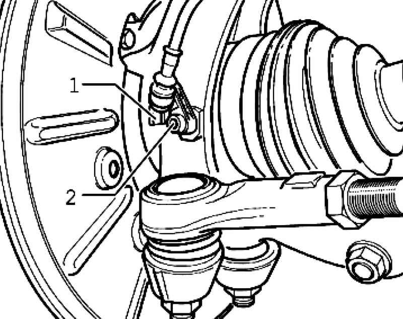
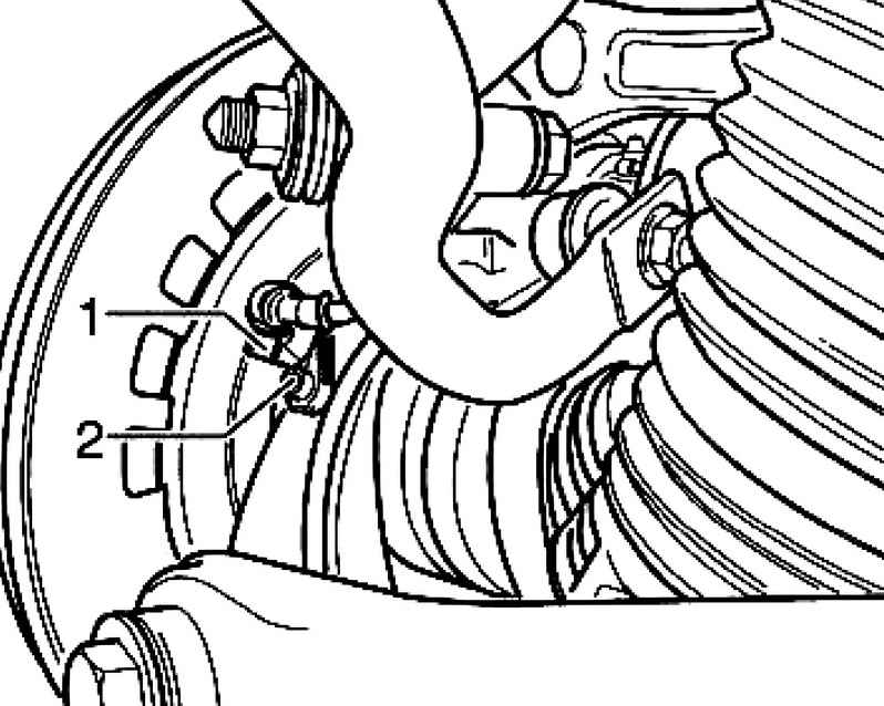
Disconnect connector 1 cable speed sensor and speed sensor (Fig. 6.66). Remove the bolt 2 from the wheel bearing housing. Remove ABS speed sensor from wheel bearing housing.
Setting Before installing the speed sensor, clean the hole and apply a little grease on the entire diameter Insert the speed sensor into the hole wheel bearing housing and tighten bolt to 8 Nm. Connect the speed sensor to the sensor cable. Removal and installation of components of system ABS on the rear axle
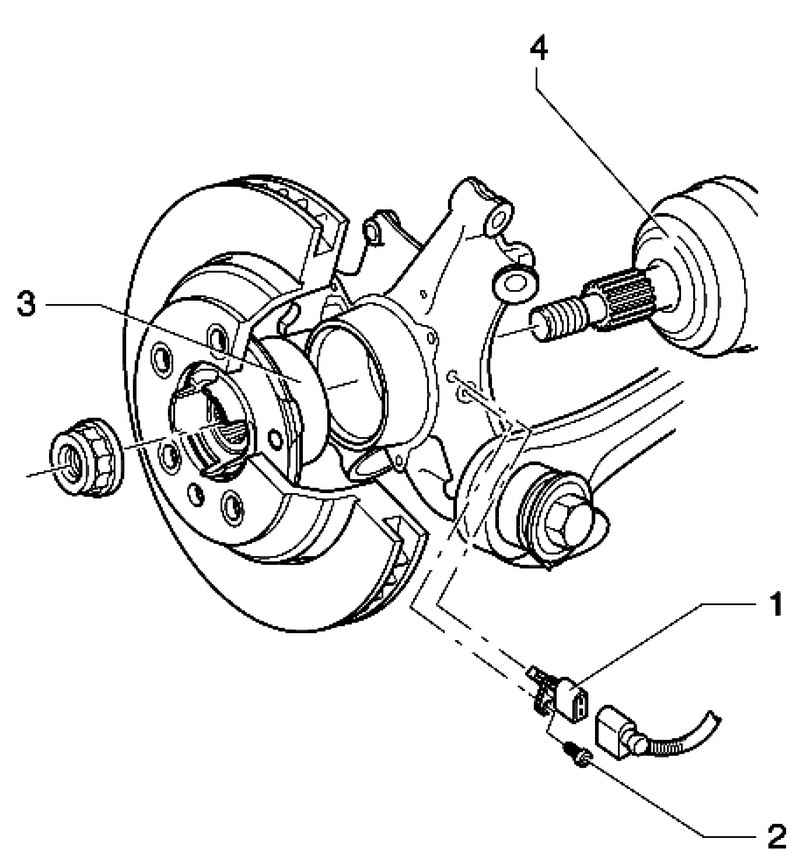
| Fig. 6.67. Components of ABS on the rear axle: 1 - speed sensor ABS; 2 - a bolt with hexagon socket, 8 Nm; 3 - wheel bearing / wheel hub assembly; 4 - drive shaft
|
Removing and installing speed sensor on the rear axle Raise the vehicle.
Disconnect connector 1 cable speed sensor and speed sensor (Fig. 6.68). Remove the bolt 2 from the wheel bearing housing. Remove ABS speed sensor from wheel bearing housing. Before installing the speed sensor, clean the hole and apply a little grease on the entire diameter Insert the speed sensor into the hole wheel bearing housing and tighten bolt to 8 Nm. Connect the speed sensor to the sensor cable.
|