printable version printable version
Removing and installing brake pads
Withdrawal Mark brake pads when they are re-used. They must be set back in its place, otherwise there is the uneven distribution of braking forces between the wheels. Remove the wheels.
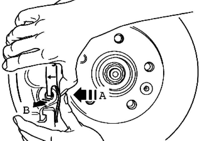
Push the retaining spring in the direction of arrow A, until it can apply pressure from the opening in the direction of arrow B (Fig. 6.26).
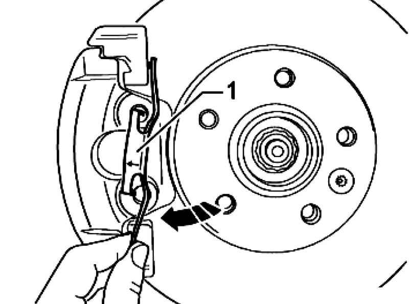
Turn retaining spring 1 clockwise until it can not be drawn from the top hole (Fig. 6.27).
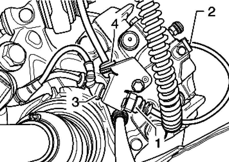
| Fig. 6.42. Removing the component cable Brake pad wear indicator
|
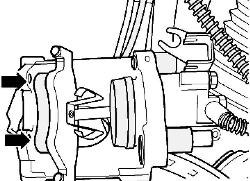
Disconnect the connector 1 Brake pad wear indicator (Fig. 6.42). Remove the display cable from the brake pad holder 2 on the brake caliper. Remove the bottom of the plug 3 Brake pad wear indicator cable and speed sensor 4 from the holder on the brake caliper.
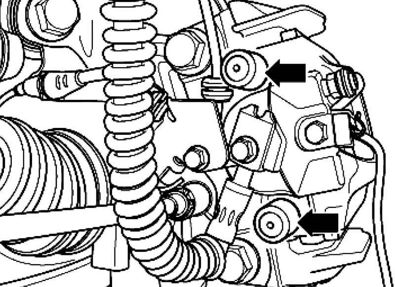
Unscrew and remove the two guide pin of the brake caliper. Remove the brake caliper and strengthen its wire so that it does not pull its weight on the brake hose and do not damage it. Remove the brake pads. Clean the supporting surface of brake pads in the caliper-holder, remove the corrosion. Clean the brake caliper. To clean the brake caliper using only alcohol.
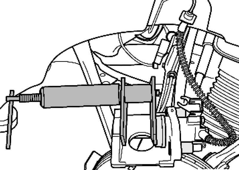
Setting Before dent the piston in the cylinder using a special device, it is necessary to pump the brake fluid reservoir. Otherwise, in the case of topping a liquid, it can leak and cause damage.
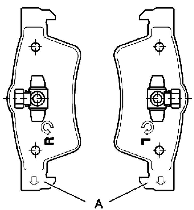
NOTE Internal brake pads (on the side of the piston) are set to determine the direction of motion, so they should be the mark. |
Brake pads that are set to determine the direction dvizheniyav installed state on the back of the brake pad should show downwards (in the direction of rotation of the brake disc) (Fig. 6.45).
Install the brake pads with retaining springs into the piston (Fig. 6.46). Install the outer brake pad in the bracket holder. Secure brake caliper two guide bolts on the bracket-holder. Set both the cap. Press the cable speed sensor 4 in the holder on the brake caliper. Connect plugs 3 and 1 brake pad wear indicator in the holder on the brake caliper. Secure the cable brake pad wear indicator in the holder 2 on the brake caliper. Install the retaining spring in the upper hole, then turn it clockwise. Install the lower retaining spring on the bracket holder. Then click on the first retaining spring in the direction of arrow A and then simultaneously opening the brake caliper in the direction of arrow B (Fig. 6.26). Install the wheels.
NOTE After each replacement brake pad several times strongly press on the brake pedal. This is necessary to ensure that the brake pads have taken their position. |
After replacing the pads, check the brake fluid level.
Torque Brake caliper to the bracket-holder: 30 Nm.
|