add to favorites contacts sitemap
REPAIR MAINTENANCE OPERATION OF MOTOR VEHICLES
Volkswagen Touareg (from 2003 to 2006, the year of issue)

general info. full specifications. diagnostics. hints. tips. tricks
Volkswagen Touareg
Home
 
Volkswagen
Touareg
Operation and maintenance of car
Engine
Transmission
Chassis
Steering Gear
Brakes
Overview
Example data plate car
Front brakes
Rear brakes
Check the brake system
Bleeding brake system
Bleeding (major)
Additional pumping
The sequence of pumping
Removal and installation of the membrane potentiometer stroke brake booster G420
Removal and installation of the vacuum pump the brakes V192
Removing and installing brake servo pressure sensor G294
Removal and installation of the main brake cylinder
Removing and installing brake booster
Repair the brake pipe
Repairing front brake, Brembo brake calipers 17 '' (1LC)
Removing and installing brake pads
Repair rear wheel brakes, brake caliper FN 44
Removing and installing brake pads
Adjusting the parking brake
Adjust the brake pads on two wheels
Checking freewheel lever parking brake pedal
Removal and installation of the lever of the foot parking brake
Removing and installing rear brake cables
Disconnecting the brake pedal from the brake booster
Connecting the brake pedal to the brake booster
Removal, installation and adjustment of brake light switch
Anti-lock braking system (ABS)
Tables
Onboard electric
Body
diagrams


Hit Counter by Digits


print page printable version

Disconnecting the brake pedal from the brake booster


ATTENTION
The course of the brake pedal should not interfere with additional mats.

The brake pedal (automatic gearbox)
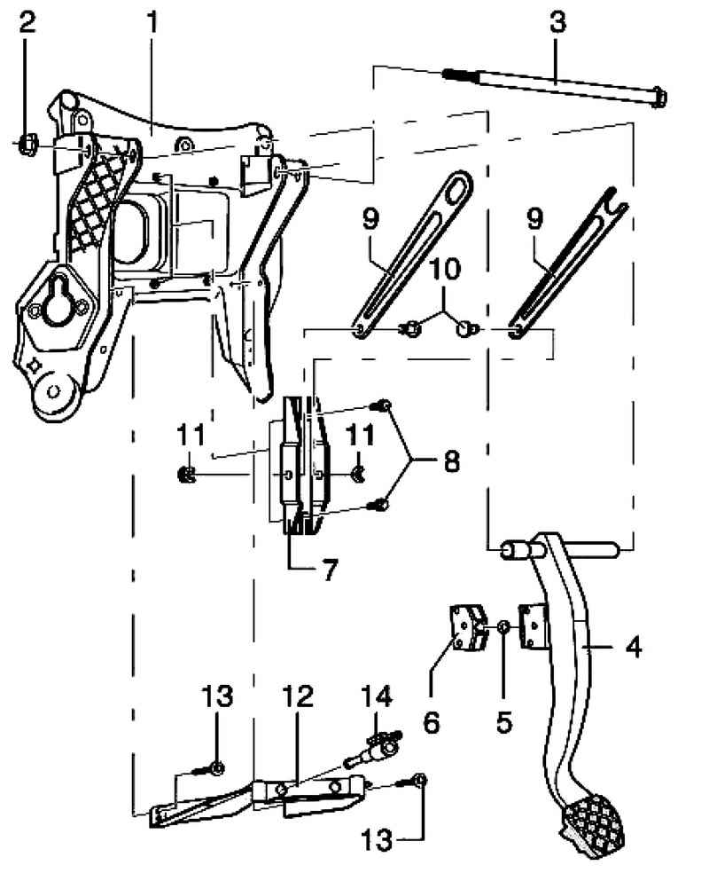
Fig. 6.57. The brake pedal (automatic gearbox): 1 - the pedal assembly support bracket; 2 - hexagon nut, self-locking, 20 Nm; 3 - finger; 4 - the brake pedal; 5 - bearing; 6 - the support bracket; 7 - a support; 8 - hex bolt, 8 Nm; 9 - hinge support; 10 - a bolt; 11 - lock washer; 12 - bracket; 13 - hex bolt, 8 Nm; 14 - brake light switch and the brake pedal sensor


Installation Tool
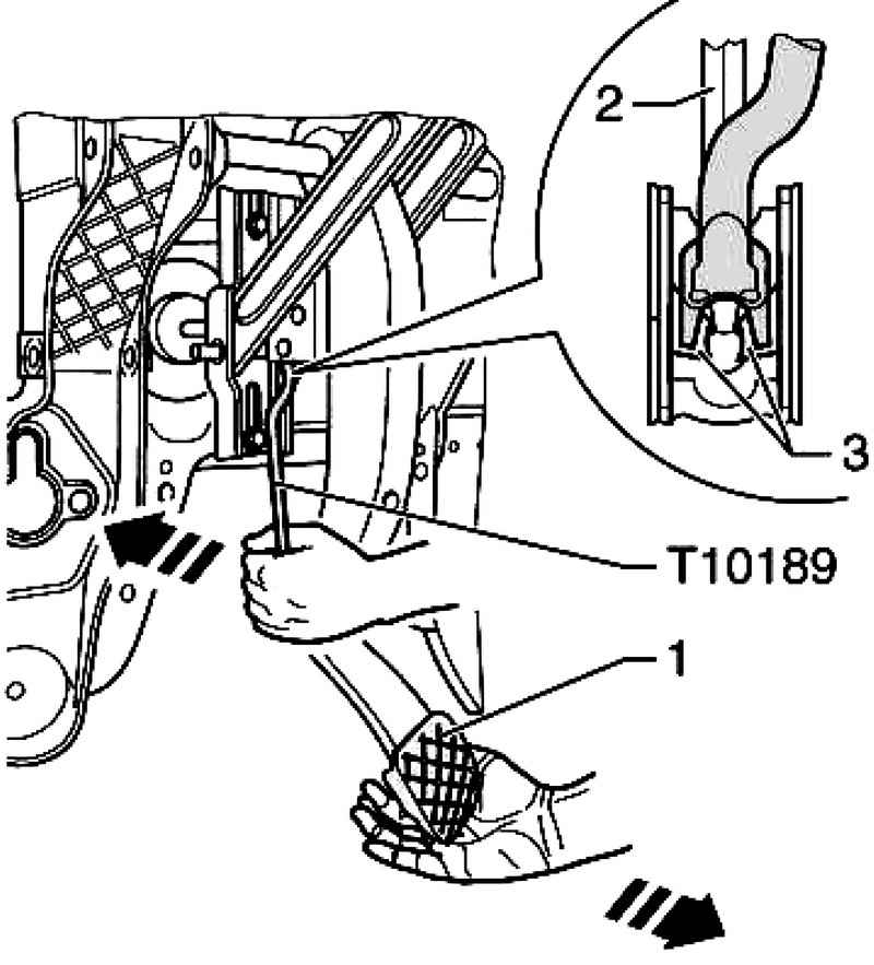
Fig. 6.58. Installation tools: 1 - the brake pedal; 2 - the push rod; 3 - Pull-tabs


Place the tool T10189 to mount the push rod in the brake pedal and support bracket (Fig. 6.58).
First, a little tap on the brake pedal in the direction of the brake booster and hold in this position.
Then push in the direction of tool T10189 brake booster, thus hold the brake pedal (pedal should not move at this time ago). Thus Pull tabs 3 are pressed mounting ball head push rod 2 (Fig. 6.58).
Press tool T10189 further in the direction of the brake booster and brake pedal at the same time pull in the direction of the driver's seat. (Thereby the brake pedal is moving away from the ball head push rod).


« previos page
Removing and installing rear brake cables
next page »
Connecting the brake pedal to the brake booster

Copyright © 2010 AutoManuals.biz. Trademarks belong to their respective owners. All rights reserved.