printable version printable version
Repair the brake pipe
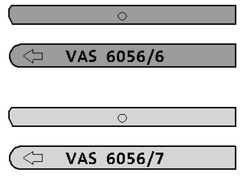
With the device for pipes VAS brake 6056 can be flared tube with an external diameter of 5 mm without damaging the coating. With this in certain cases possible to replace individual parts of the brake pipe, which reduces the cost of repairs. Using the device for pipes VAG 1356 on the black brake lines are not allowed because of their cover and diameter.
NOTE Brake lines are allowed to bend no more than 90 ?°, otherwise they may break or deform, so much that is critical to reduce their orifice. The connection point is better placed under the vehicle. Coupling should be positioned so that they do not touch moving parts and components. Spindle not grease, but only clean with alcohol. |
The arrow on the round side clamps must point to the edge of the body and straight side clamps must be installed to the spindle, otherwise improperly formed flaring head (Fig. 6.19).
Carrying out works Remove the brake line from the caliper or the appropriate wheel brake cylinder. Collect and properly dispose of the brake fluid.
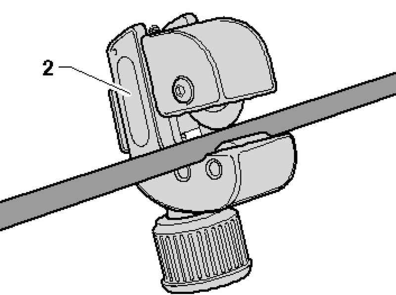
Cut the pipe at a suitable point (no bends, easy access) using the 2 (Fig. 6.20). Remove the damaged area. Remove the shell at the end of the pipeline.
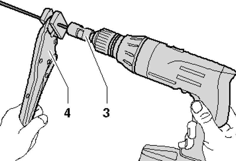
Clamp brake tube clamp 4 in such a manner that about 50 mm projecting from the plastic of the jaws (Fig. 6.21). Set the nozzle to remove the lining 3 on the drill and insert the nozzle end of the pipeline. Cut shell slowly rotating nozzle and easily pushing the drill. Stripping length of the nozzle is determined by the depth (cut off the way). Remove the nozzle from the brake pipe and clean it from the chips.
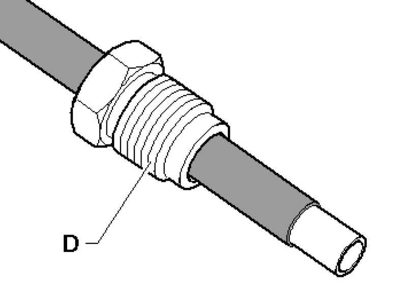
Remove the pipe from the vise hand and put on his nipple D (Fig. 6.22).
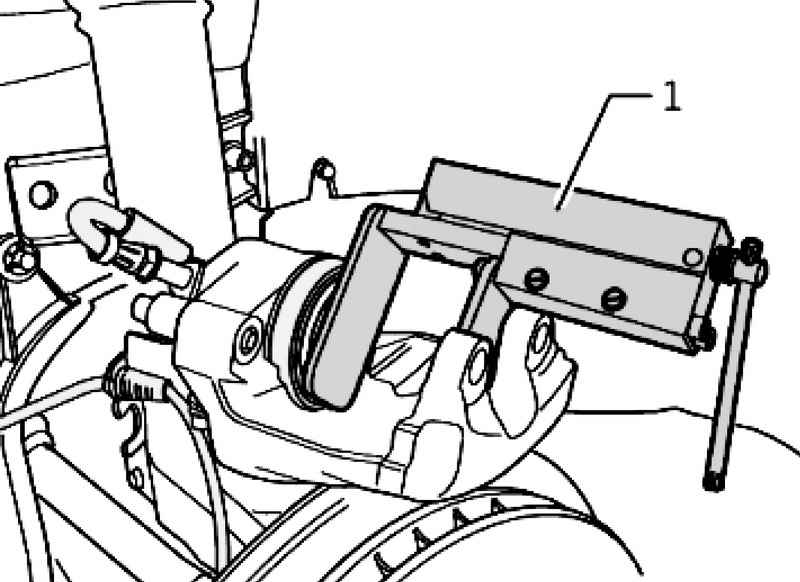
| Fig. 6.23. Installation of the pipeline means for expanding
|
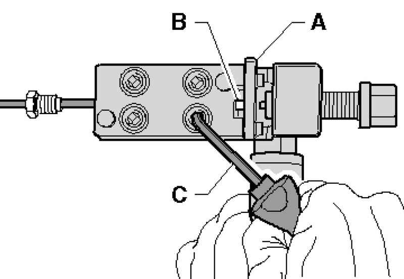
Insert the conduit B to lock A device for expansion (Fig. 6.23).
NOTE When tightening the Allen screw brake pipe shall conform to the fence, otherwise the handset will be expanded correctly. |
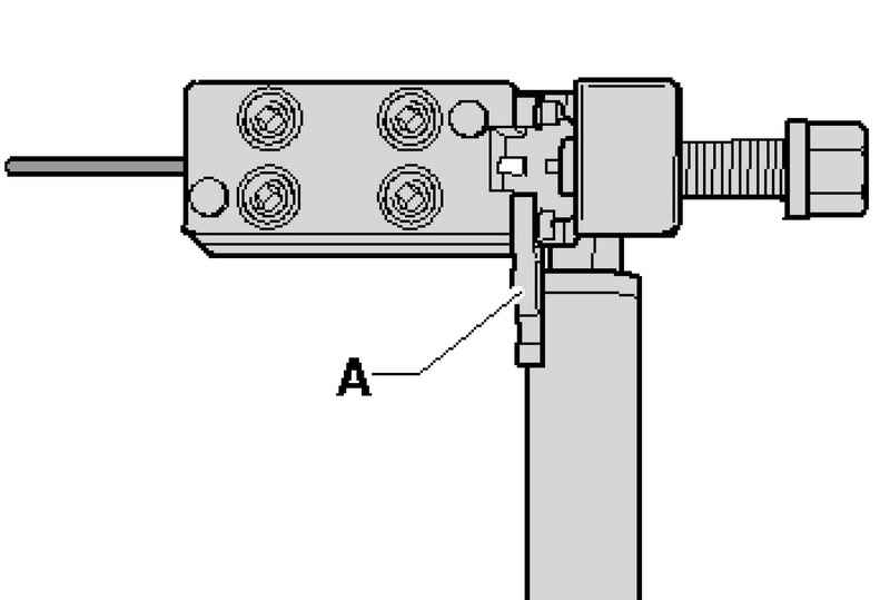
Clamp the pipe in the device for expansion, so he could not move freely in it. Pull the focus A and tighten crosswise Allen screws using the bracket C.
Screw the spindle into the device until it stops (Fig. 6.24). Remove the spindle to its original position. Crosswise, loosen the Allen screw. Remove the brake line from the device, clean and inspect the pipeline and flaring. Flush mounted car brake pipe. Connect the device for filling and bleeding the brake system VAS 5234, put on a flared end of the hose pipe to pump the tank and turn on the device for a short time for filling and bleeding the brake system VAS 5234 to the brake fluid flushed filings. Blow compressed air pipe installed.
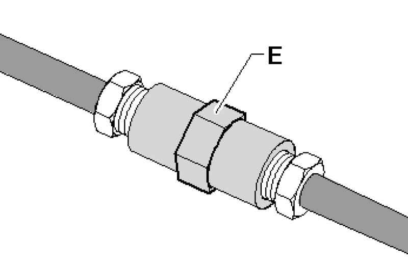
Connect the brake pipes with the help of the union E (Fig. 6.25). Secure the brake lines. Bleed the brake system.
Removing and installing brake pads Withdrawal Mark brake pads when they are re-used. They must be set back in its place, otherwise there is the uneven distribution of braking forces between the wheels. Remove the wheels.
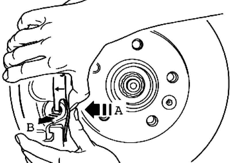
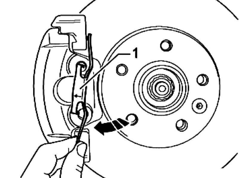
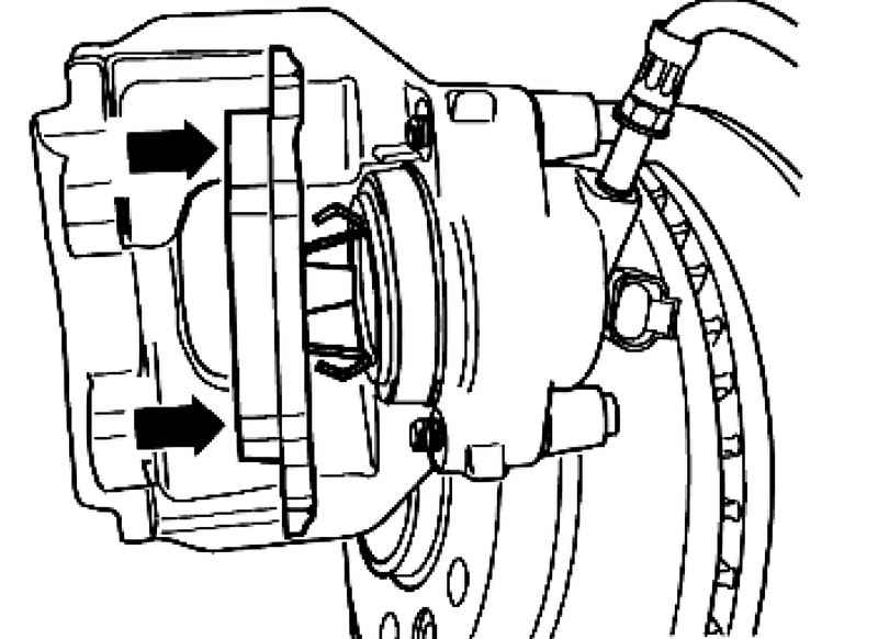
Squeeze the retaining spring in the direction of arrow A, until it can apply pressure from the opening in the direction of arrow B (Fig. 6.26).
Turn retaining spring 1 clockwise until it can not be drawn from the top hole (Fig. 6.27).
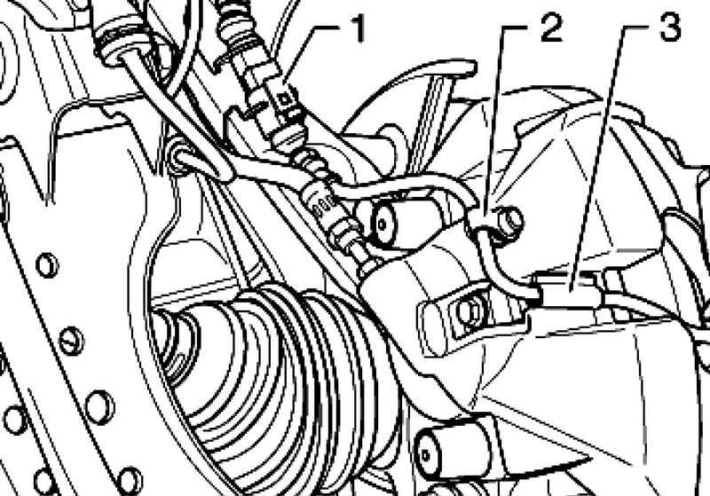
| Fig. 6.28. Removing the component cable Brake pad wear indicator
|
Disconnect the connector 1 Brake pad wear indicator, remove the cap 2 and remove the cable brake pad wear indicator (Fig. 6.28). Remove the display cable from the brake pad holder 3 on the brake caliper.
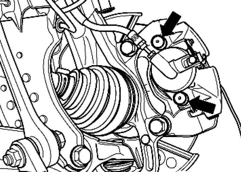
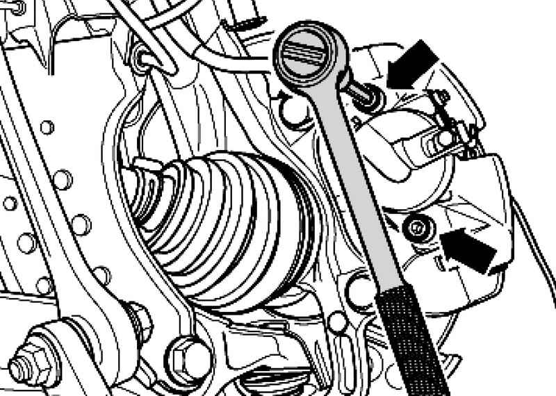
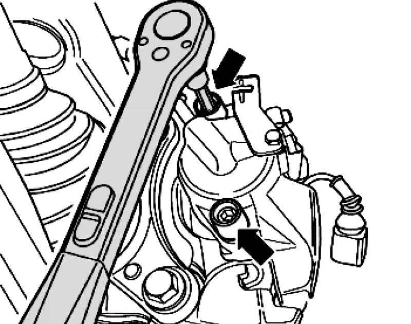
Unscrew and remove the two guide pin of the brake caliper (Fig. 6.30). Remove the brake caliper and strengthen its wire so that it does not pull its weight on the brake hose and do not damage it. Remove the brake pads.
ATTENTION Do not blow compressed air braking system. This gives rise to unhealthy dust. |
Clean the supporting surface of brake pads in the caliper-holder, remove the corrosion. Clean the brake caliper (remove adhesive residue) - adhesive surface must be dry and clean. To clean the brake caliper using only alcohol.
Setting Before dent the piston in the cylinder using a special device, it is necessary to pump the brake fluid reservoir. Otherwise, in the case of topping a liquid, it can leak and cause damage.
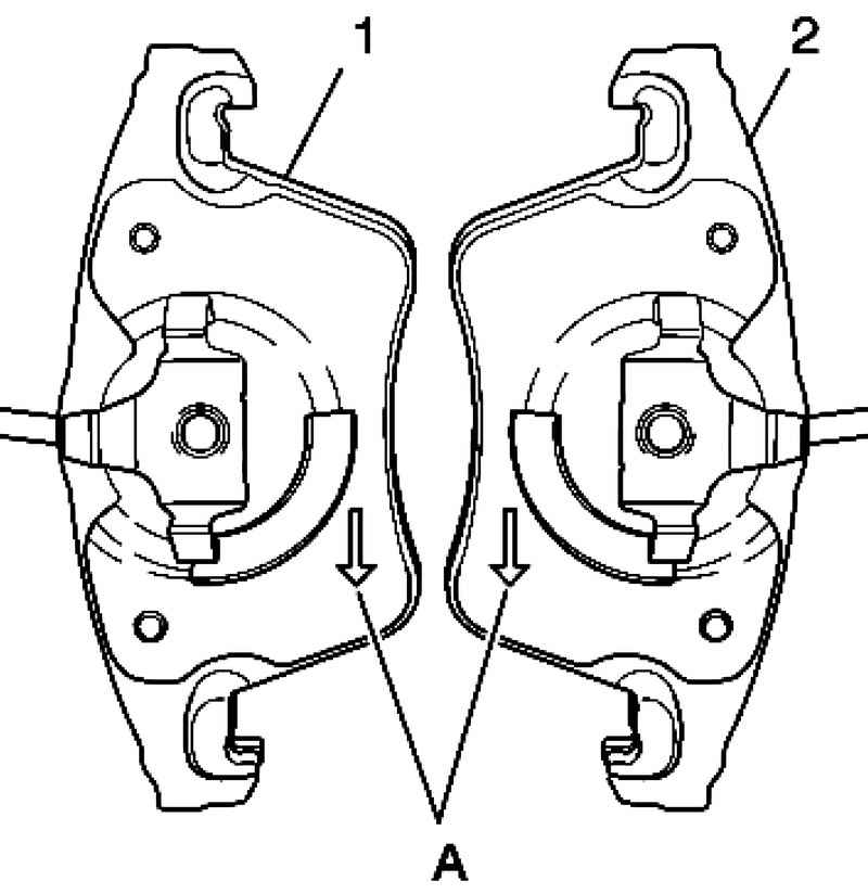
NOTE Internal brake pads (on the side of the piston) are set to determine the direction of motion, so they should be the mark. |
| Fig. 6.32. Brake pads: 1 - right-hand brake shoe on the side of the piston; 2 - the left brake shoe on the side of the piston
|
In the installed state of the arrow A to the reverse side of the brake pad should exhibit downward (in the direction of rotation of the brake disc).
Install the brake pads with retaining springs into the piston (Fig. 6.33). Remove the backing from the base plate of the outer brake pad.
When installing the brake caliper, take care that the brake shoes are not glued to the brake caliper up to the proper mounting position.
Secure brake caliper two guide bolts on the bracket-holder (Fig. 6.35). Set both the cap. Connect the plugs 1 Brake pad wear indicator in the holder on the housing of the wheel bearing (Fig. 6.28). Secure the cable brake pad wear indicator with a cap on the bleeder plug 2 holder 3 on the brake caliper. Install the retaining spring in the upper hole, then turn it clockwise (Fig. 6.27). Install the lower retaining spring on the bracket holder. Then click on the first retaining spring in the direction of the arrow A, and then at the same time opening the brake caliper in Escrow arrow B (Fig. 6.26). Install the wheels.
NOTE After each replacement brake pad several times strongly press on the brake pedal. This is necessary to ensure that the brake pads have taken their position. |
After replacing the pads, check the brake fluid level.
Torque Brake caliper to the bracket-holder: 30 Nm.
|