printable version printable version
Removing and installing sealing ring flange PTO / PTO drive shaft and motor transfer case
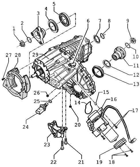
| Fig. 3.107. The components of the transfer case 1 - nut 130 Nm; 2 - O-ring; 3 - a flange PTO; 4 - Metal Bellow; 5 - O-ring; 6 - ventilation tube; 7 - a sealing ring of a primary shaft; 8 - O-ring; 9 - nut 130 Nm; 10 - O-ring; 11 - flange PTO; 12 - Metal Bellow; 13 - a sealing ring; 14 - O-ring; 15 - mounting sleeve; 16 - electric transfer case; 17 - bolt 27 Nm; 18 - bolt 14 Nm; 19 - a collar; 20 - Oil drain plug, 20 Nm; 21 - a bolt, 20 Nm; 22 - bolt 20 Nm; 23 - the console; 24 - oil temperature sensor 17 Nm; 25 - a sealing ring; 26 - a bolt hole for the Gulf oil 20 Nm; 27 - bolt 32 Nm; 28 - damper; 29 - transfer case
|
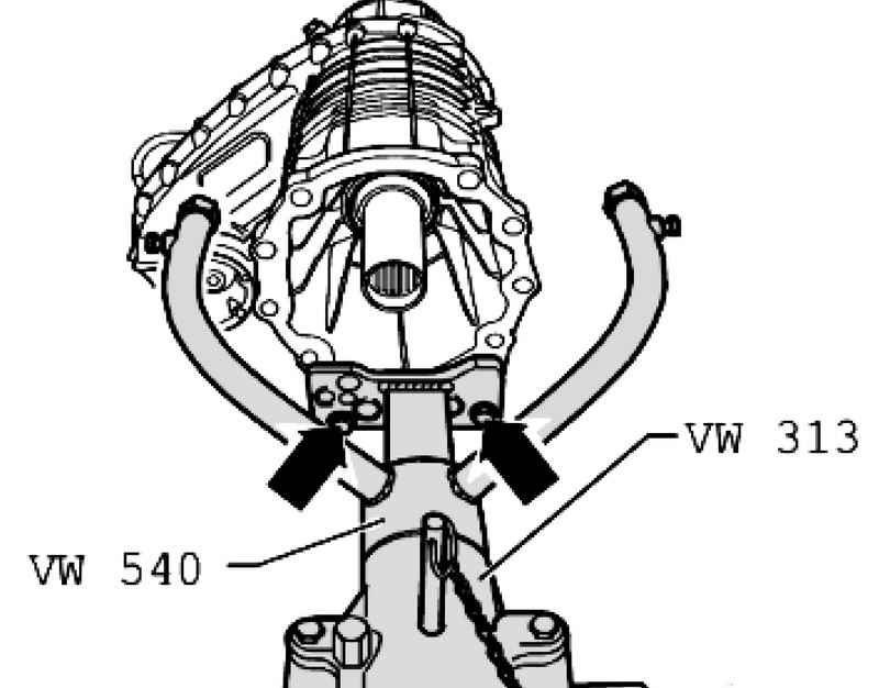
| Fig. 3.108. Install the transfer case on the pasteboard
|
Secure transfer case to the mounting stand with screws (Fig. 3.108).
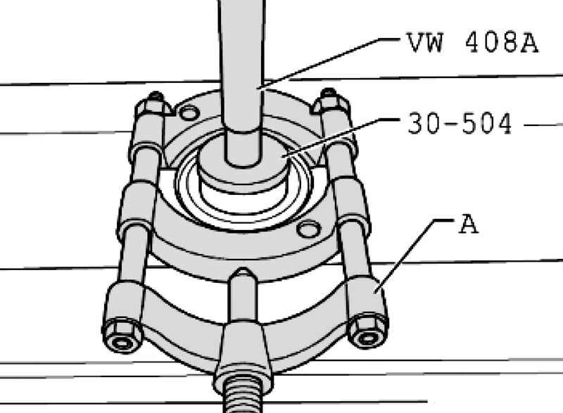
A - puller 22-115 mm, for example, Kukko 17/2.
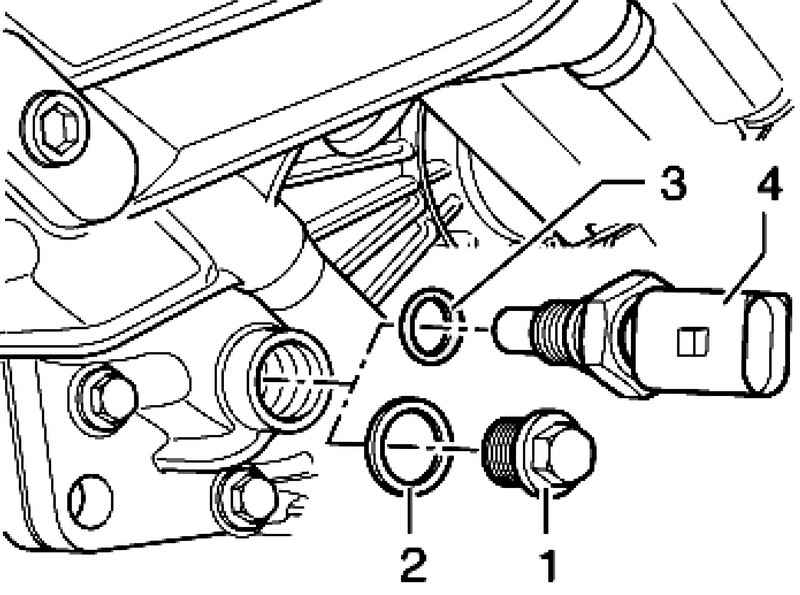
Remove the O-ring flange PTO / rear propeller shaft.
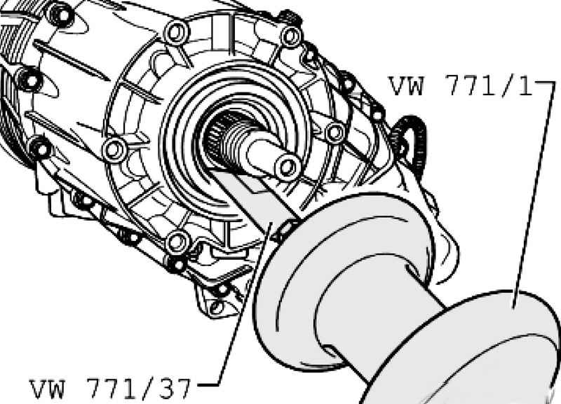
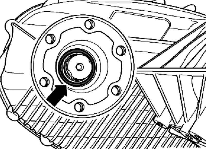
| Fig. 3.111. Removing the O-ring flange PTO / rear propeller shaft
|
Figure 3.111 shows the removal of the O-ring flange PTO / rear propeller shaft. Progress on removal of the O-ring flange PTO / front propeller shaft is similar.
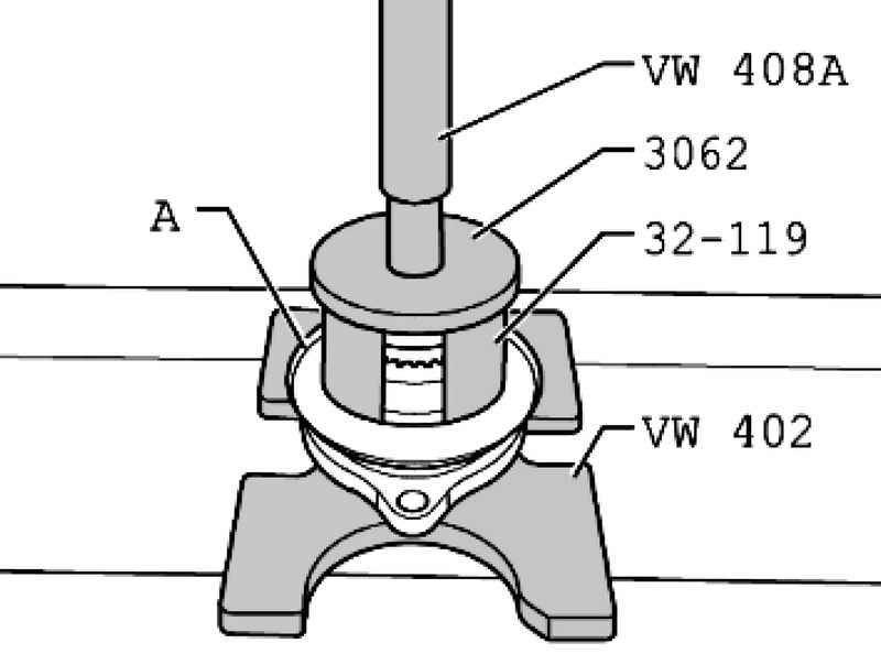
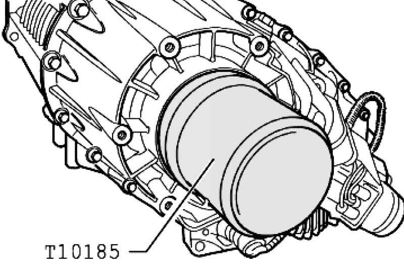
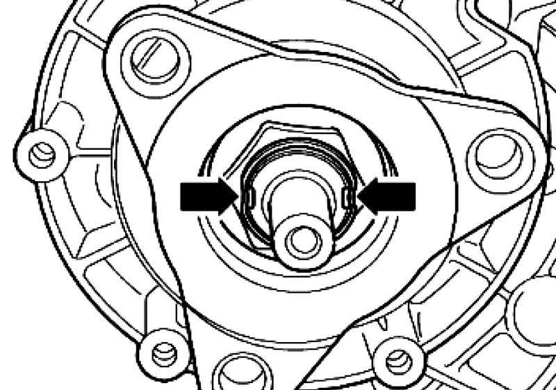
| Fig. 3.112. Pressing the O-ring flange PTO / rear propeller shaft
|
Fitting the seal ring flange PTO / rear propeller shaft (Fig. 3.112). Fill the space between working with the dust and sealing lips half with grease G 052 128 A1. Install O-ring into the groove of the input shaft. Fitting the seal ring flange PTO / front propeller shaft. Fill the space between working with the dust and sealing lips half with grease G 052 128 A (Fig. 3.112). Remove the vent pipe A. Insert mandrel with O 5 mm hole in the vent tube.
| Fig. 3.113. Removing the vent tube from the transfer case
|
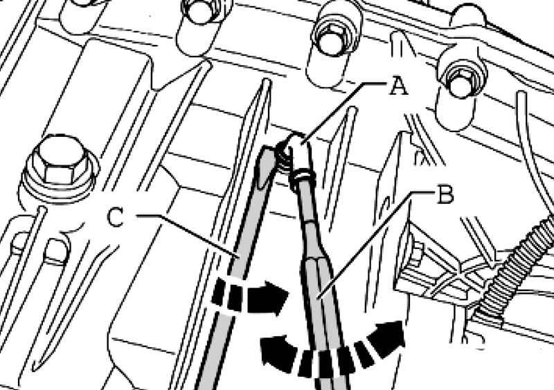
Moving A vent tube in the direction of the arrow, at the same time lift it with a screwdriver and remove the C vent tube from the transfer case (Fig. 3.113).
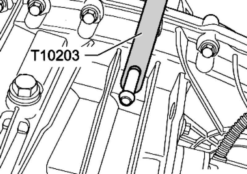
Lubricate before pressing the ventilation tube nail fixing Loctite 648. A method of repair when replacing the motor transfer case V253 and faulty oil temperature sensor G8
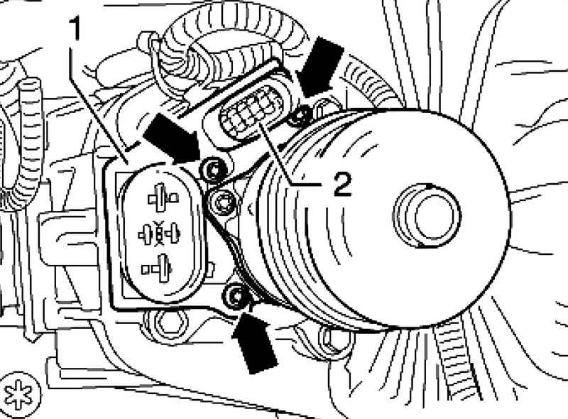
When replacing the motor transfer case V253 and failure oil temperature sensor 4 is necessary, replace the oil temperature sensor (with O-ring 3) through the drain plug 1 with O-ring 2 (Fig. 3.115). Dismantling harness the oil temperature sensor G8 takes place in the following order. Remove the holder 1 Plug motor transfer case, this unscrew bolts.
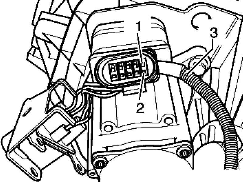
Remove the wires 1 and 2 of the 10-pin connector with a suitable tool set for repair of cable VAS 1978.
| Fig. 3.117. Harness and opening the 10-pin connector
|
Disconnect the wiring harness 3 oil temperature sensor (Fig. 3.117). Close the holes for the wires 10-pin connector 1 and 2 with a suitable plug. Changing the O-ring flange PTO / front propeller shaft (transfer box set) Withdrawal Remove the front driveshaft.
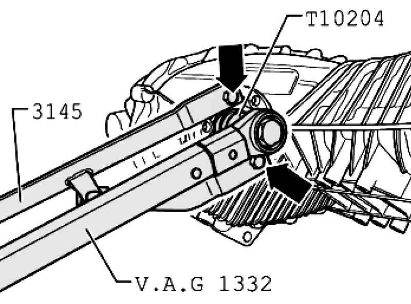
Secure counter support 3145 2 M10x25 bolts on the flange PTO (Fig. 3.118). Loosen flange nuts PTO. Remove the flange PTO. Remove the seal ring with a general purpose tool VW 771 and stripper VW 771/37. Clean the threads of the screws.
Setting Fill the space between working with the dust and sealing lips half with grease G 052 128 A1. Fitting the new sealing ring to the end, it does not distort it (Fig. 3.112). Install flange PTO.
The new O-ring in the transmission oil to moisten and set (Fig. 3.119). Grease the threads of the new screws nail fixing Loctite 648. Fasten the nuts on the specified places (eg mandrel).
| Fig. 3.120. Fixing nuts on the flange PTO / rear propeller shaft
|
The figure shows the fastening nuts on the flange PTO / rear propeller shaft (Fig. 3.120). Install the front propeller shaft. Check the oil level in the transfer case Torque: flange nuts PTO to PTO 130 Nm
|