add to favorites contacts sitemap
REPAIR MAINTENANCE OPERATION OF MOTOR VEHICLES
Volkswagen Touareg (from 2003 to 2006, the year of issue)

general info. full specifications. diagnostics. hints. tips. tricks
Volkswagen Touareg
Home
 
Volkswagen
Touareg
Operation and maintenance of car
Engine
Transmission
Chassis
Wheels and tires
General information on wheels and tires
Technical conditions for the conversion of wheels and tires
Indexes of speed of tires
Markings on the disk
Composite wheels
Depreciation and divergence tires
Wear high-speed tires
Tyre service
Evenly worn tires
Measure the tread depth
One-sided wear
Diagonal uneven wear
Tire rolling noise
Balancing
Radial and lateral palpation of wheels and tires
Check of radial and lateral palpation of a disk with the tire by using a dial gauge for tires VAG 1435
Minimization
Lateral withdrawal of the car
Eliminating slip
Damage to tires
The design of the radial tire
Loss of air pressure in the tires
Damages of tires because of errors at mounting (assembly damages)
Marking the tire sidewall
Shift of wheels
Touareg 2003 model year
Repair of control system of air pressure in the tires
Removing and installing control unit, tire pressure monitoring J502
Repair of control system clearance
The components of the control system and clearance fitting locations
Removal and installation of the compressor unit without solenoid valve
Repair air line
Front suspension
Rear suspension
Tables
Steering Gear
Brakes
Onboard electric
Body
diagrams


Hit Counter by Digits


print page printable version

Removal and installation of the compressor unit without solenoid valve


Withdrawal
Remove bottom right trim.

The suction pipe couplings
Fig. 4.40. The suction pipe couplings


Disconnect the suction pipe 1 at the coupling (Fig. 4.40).
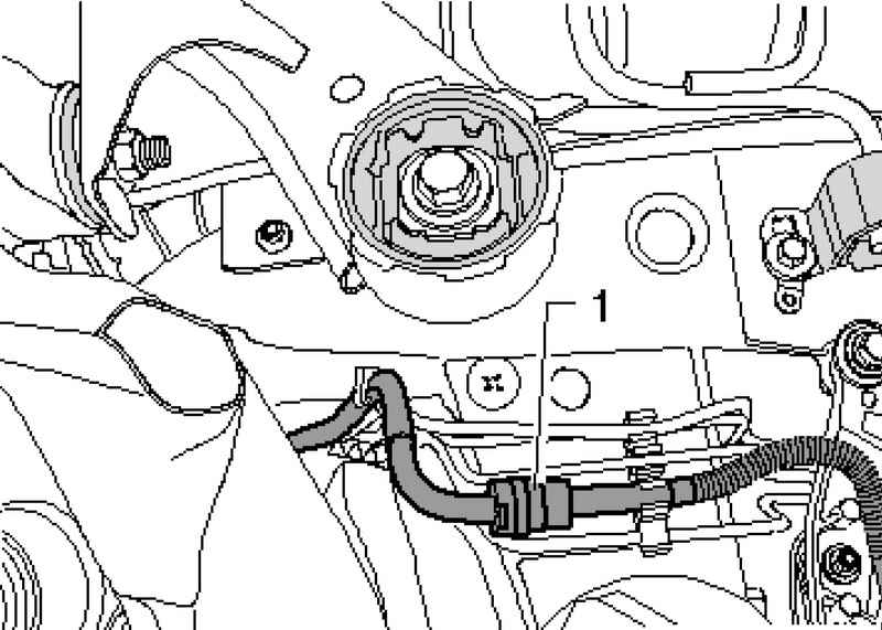
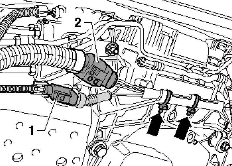
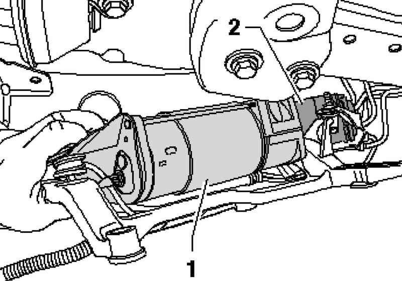
Disconnect the electrical connection between 1 and 2 and the compressor body.

Yokes
Fig. 4.41. Yokes


Remove the clamps (Fig. 4.41).

The airway tube
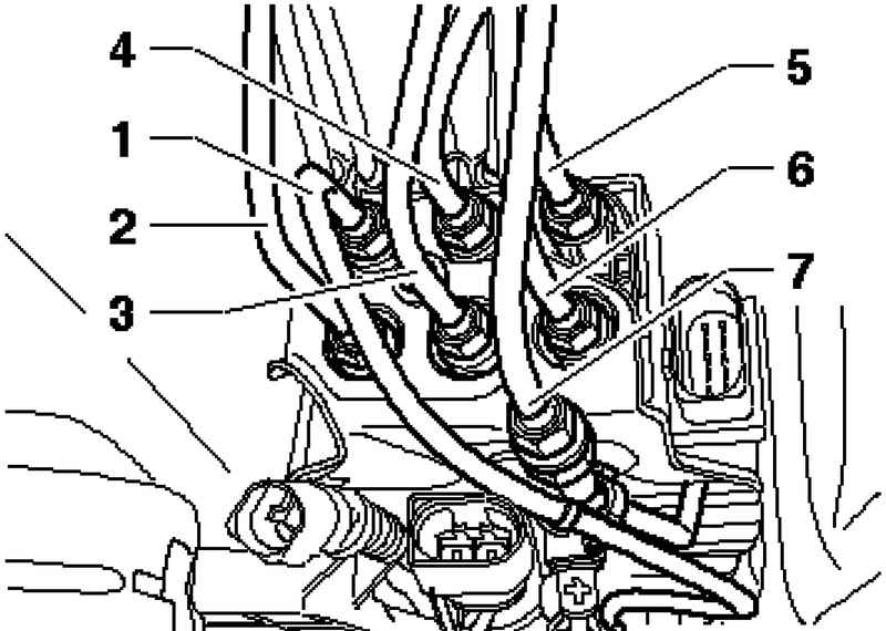
Fig. 4.42. Airway tube: 1 - black, inner conduit between the power of the solenoid valves and compressor; 2 - green, the air line to the front right elastic Pneumoelements; 3 - red, the air duct to the rear left elastic Pneumoelements; 4 - purple, the air line to the front left elastic Pneumoelements; 5 - blue, the air line to the accumulator; 6 - yellow, the air line to the right rear elastic Pneumoelements 7 - brown, the air line connections for tire inflation


Remove the air duct 1 from the solenoid valve block (Fig. 4.42). Disconnect the pipe from the coupling 7.

ATTENTION
To remove the air lines 2 through 6 are not permitted.

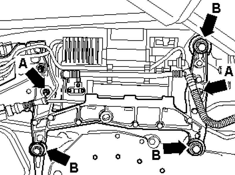
Remove the air lines from the holder on the bottom.
Remove the nuts A compressor.

Fastening of the compressor
Fig. 4.43. Fastening of the compressor


Remove the bolts B, then the assistant should secure the compressor to the holder (Fig. 4.43).

Removing the compressor
Fig. 4.44. Removing the compressor


Compressor with lower holder forward so that the compressor 1 can be removed (Fig. 4.44).

ATTENTION
Make sure that the solenoid valve block 2 has been removed from the bottom as low as possible.
In addition, in any case not allowed to bend or stretch of air.

Setting
Installation is carried out in reverse order.

Tightening torques
Air pipes to block solenoid valves: 4 Nm.
Holder to the body: 20 Nm.
Compressor to the holder 6 Nm.


« previos page
The components of the control system and clearance fitting locations
next page »
Repair air line

Copyright © 2010 AutoManuals.biz. Trademarks belong to their respective owners. All rights reserved.