printable version printable version
Repair of control system of air pressure in the tires
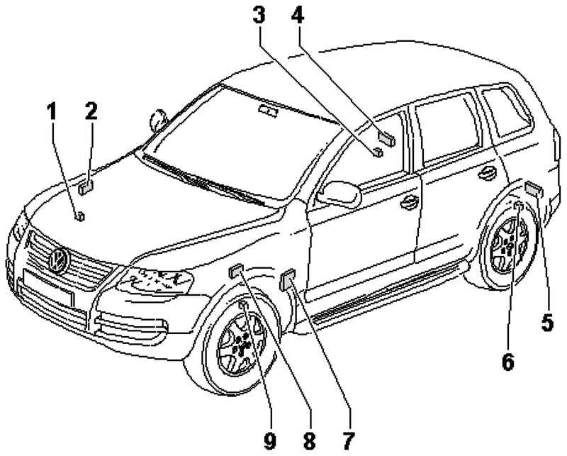
The components of the control system tire pressure (Fig. 4.31).
| Fig. 4.31. The components of the control system tire pressure: 1 - front right tire pressure sensor; 2 - Antenna for the front right pilot pressure indicator; 3 - Rear right tire pressure sensor; 4 - antenna for the rear right control pressure indicator; 5 - antenna rear left control pressure indicator; 6 - left rear tire pressure sensor; 7 - control system, tire pressure monitoring; 8 - antenna for the front left indicator control pressure; 9 - front left tire pressure sensor |
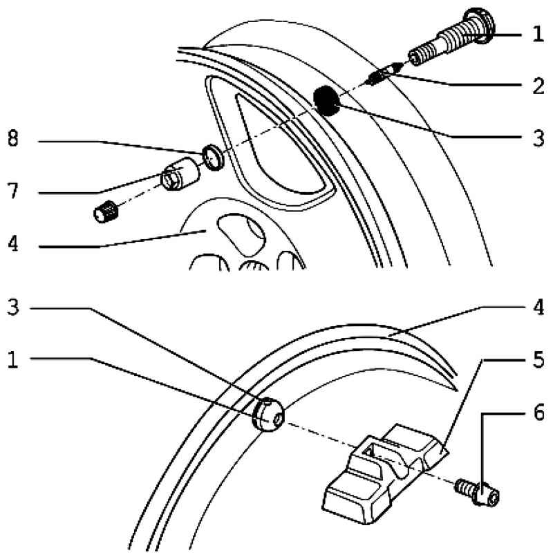
| Fig. 4.32. The pressure sensor in the tire and a metal gate: 1 - a metal gate; 2 - spool valve; 3 - O-ring; 4 - wheel drive; 5 - a pressure sensor in the tire; 6 - screw Torx T20; 7 - a nut; 8 - a washer
|
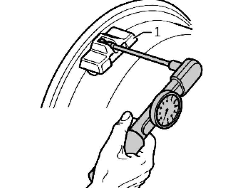
Removing the tire pressure sensor
At the same time hold the metal gate by a counter support (eg drill 2 mm)
Removing the metal gate
At the same time hold the metal gate by a counter support (eg drill 2 mm).
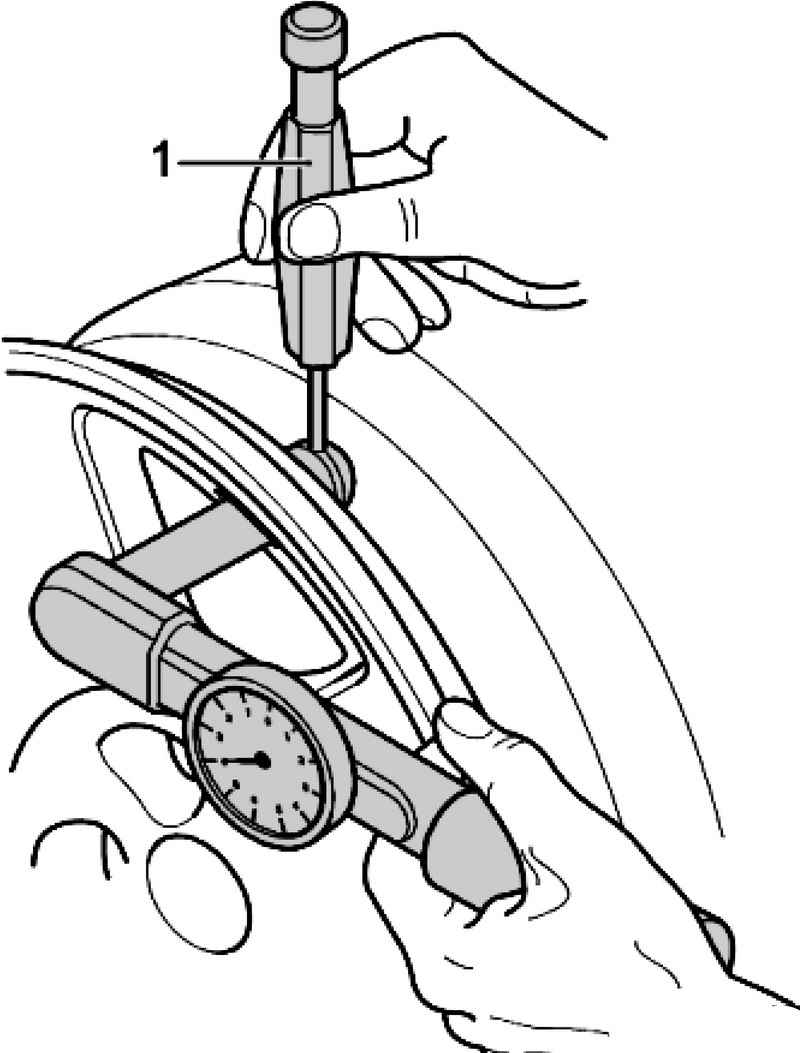
Installing metal gate Tighten the valve. At the same time hold the metal gate by a counter support (eg drill 2 mm).
Set the tire pressure sensor Press the pressure sensor 1 to the disk (rim) and tighten. At the same time hold the metal gate by a counter support (eg drill 2 mm). After installation on the vehicle wheel must be stored in memory in the tire air pressure
Torque The pressure sensor in the tire to the metal gate 4 Nm. Hex nut to a metal gate: 7 Nm.
Set the tire pressure sensor Press the pressure sensor 1 to the disk (rim) and tighten. At the same time hold the metal gate by a counter support (eg drill 2 mm). After installation on the vehicle wheel must be stored in memory in the tire air pressure.
Torque The pressure sensor in the tire to the metal gate 4 Nm. Hex nut to a metal gate: 7 Nm.
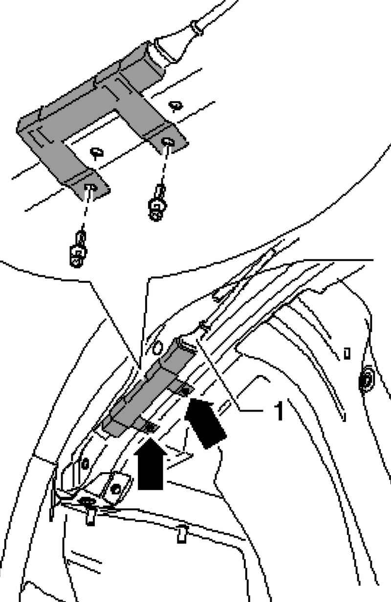
Removing the antenna front control pressure indicator Antennas front control pressure indicator set for the wing flaps on the side member. Switch off the ignition. Remove the liner. Disconnect the connector 1.
| Fig. 4.35. Removing the antenna front control pressure indicator
|
Remove the rivets with a notch, and remove the antenna front control pressure indicator (Fig. 4.35).
Installing the antenna front control pressure indicator Insert the antenna front control pressure indicator and fasten it with new rivets scored. Connect the connector 1. Install the liner.
Removing the rear antenna control pressure indicator Antennas adjustable control pressure indicator set for the wing flaps on the side opposite the direction of movement. Switch off the ignition. Remove the liner. Disconnect the connector 1.
| Fig. 4.36. Removing the rear antenna control pressure indicator
|
Remove the rivets with a notch, and remove the antenna control back pressure indicator (Fig. 4.36).
Installing the antenna control back pressure indicator Insert the antenna control back pressure indicator and fasten it with new rivets scored. Connect the connector 1. Install the liner
|