printable version printable version
Timing belt and accessory drive
Replace the timing belt and accessory drive carried out as follows: 1) Remove the cover of the engine;
| Fig. 2.56. Loose accessory drive belt
|
- Release the accessory drive belt, pulley unscrewing the screw clockwise; - Remove the accessory drive belt; - Release the belt tensioner (counterclockwise); - Remove the accessory drive belt; 3) Unscrew the top cover of the timing belt and remove it; 4) Install a lifting beam 999 over the 5006 engine in the middle and insert the lifting hook 999 in 5460 lifting eye, if necessary, install additional bracket 999 5383; 5) Lift the motor a few millimeters;
| Fig. 2.57. Mounting the engine support
|
6) Remove the motor support on the part of the camshaft (Fig. 2.57), as follows: - Remove the screw from the support on the body; - Unscrew the two screws and remove the screw from the engine mounts; - Remove the support together with a rubber component; 7) on cars with air conditioning, disconnect the hose from the bracket, unscrew the two screws and remove the bracket;
| Fig. 2.58. Removing the bottom cover of the timing belt
|
8) Remove the lower timing belt cover (Fig. 2.58), as follows: - Remove the screw (arrow); - Remove the driven pulley; - Remove the bottom cover of the timing belt; 9) Remove the right front wheel, which should: - Put a support under the vehicle; - Remove the wheel; - Slightly loose cover;
| Fig. 2.59. Remove the crankshaft pulley
|
- Turn out four bolts of fastening of a pulley; - Set the tool 999 5433 and fix it with four bolts; - Unscrew the central nut; - Slightly lower the engine (if necessary); - Remove the tool;
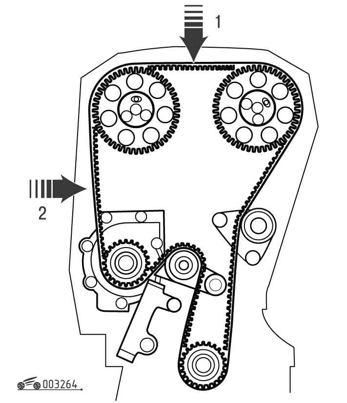
| Fig. 2.60. Combining marks Timing
|
| Fig. 2.61. Removing the timing belt
|
- Set the mark (see. Prev. Para) facing each other; - Turn out the top bolt (arrow) of the tensioner; - Loosen the bottom bolt (arrow); - Turn the tensioner so that the pulley rotates freely; - Turn out the bottom bolt; - Remove the tensioner; - Remove the timing belt; - Clean and check all the toothed pulleys;
| Fig. 2.62. Check the tensioner and idlers
|
13) Check the tensioner and tension rollers (Fig. 2.62), as follows: - Rotating rollers, listen to the presence of background noise in the bearings; - Make sure that the contact surfaces of the rollers are clean and smooth; - Also check whether the lever is not stuck in a roller bearing it; Check the tension wheel; - Loosen the lever and apply grease 1161246-2 bearing and contact surfaces; - Torque arm tensioner 40 Nm; - Torque tension roller 25 Nm; 14) Assemble the tensioner, as follows: - Make sure there are no signs of leaks; - Remove the plastic retaining ring with the piston rod;
| Fig. 2.63. Compress the tensioner in a special fixture and its fixing by a pin
|
- Tighten the belt tensioner with special tool 999 5456 (Fig. 2.63); - Set in the tensioner device and tighten the central nut accessories; wait a few minutes to complete the compression, and then insert the locking pin (2 mm diameter) into the piston (see. Fig. 2.63);
NOTE If there are leaks or no compressive resistance, tensioner needs to be replaced. |
15) put on a new timing belt, for which: - Set the tensioner; - Set the tension screws and tighten to 25 N ?· m; - Head of the belt around the crankshaft pulley and the right tension roller; - Head of the belt around both sprocket timing; - Head of the belt around the water pump pulley and pull it over the tensioner pulley; 16) Pull the belt, as follows: - Remove the locking pin from the tensioner;
| Fig. 2.64. The tension of the timing belt
|
| Fig. 2.65. Installing the plastic ring on the piston rod tensioner
|
17) put a new plastic ring on the piston rod tensioner (Fig. 2.65). Make sure that the plastic ring is correctly positioned in the center;
NOTE The concave edge of the retaining ring should face up. |
18) Check the belt tension, for which: - Wait about 5 minutes after adjusting the tension of the timing belt;
| Fig. 2.66. Check the tension of the timing belt special indicator
|
- 998 8500, set the indicator on the toothed belt between the toothed pulley exhaust camshaft pulley and the coolant pump (Fig. 2.66); - Consider the value of using a mirror, thus it is impossible to remove the indicator until the completion of the measurement. Average belt tension should be between 2.5-4.0 units. If the normal value is not received, the tensioner must be replaced; 19) Turn the crankshaft two turns and check the match marks on the crankshaft pulley on the camshaft sprockets and timing belt cover;
| Fig. 2.67. Install the crankshaft pulley
|
- Adjust the position of a pulley with a special tool 999 5433; - Put the central nut and tighten to 180 Nm; - Remove the tool; - Tighten the pulley bolt to 25 Nm and then tighten it to an angle of 30 degrees;
| Fig. 2.68. Install covers timing belt
|
- Put the bottom cover; - Put the driven pulley, tightening torque 25 Nm. - Put the top cover (1 screw) with a torque of 10 Nm;
| Fig. 2.69. Install accessory drive belt
|
- Clean the pulley groove; - Turn the tensioner; - Wear accessory drive belt, - Free the tensioner (counterclockwise);
| Fig. 2.70. Install engine support
|
23) set the motor support on the part of the camshaft (Fig. 2.70), as follows: - Establish a support to the engine and tighten the nuts and bolts to 67 Nm; - Insert the screw into the support on the body and gently tighten it; - Remove the lifting beam 999 5006 from the engine; - Then tighten the bolt of a support point on the body 98 Nm; - For vehicles with air conditioning need to mount the bracket on the body and the hose to the bracket; - Tighten the bolts to 10 Nm; - Start the engine and check the operation;
| Fig. 2.71. Tightening the wheel nuts
|
- Secure the cover; - Put the wheel nuts and tighten its mounting crosswise torque of 110 Nm; - Tightening pneumatic wrench, use only a torque nozzle 951 2661; - Tighten wheel nuts by hand.
NOTE Tightening nuts diagonally necessary moment is important in order to avoid stresses in the brake disc. |
|