add to favorites contacts sitemap
REPAIR MAINTENANCE OPERATION OF MOTOR VEHICLES
Volkswagen Touareg (from 2003 to 2006, the year of issue)

general info. full specifications. diagnostics. hints. tips. tricks
Volkswagen Touareg
Home
 
Volkswagen
Touareg
Operation and maintenance of car
Engine
Preliminary checks on the car
The mechanical part (petrol engines 3,2L)
The mechanical part (petrol engines 4,2L)
The mechanical part (diesel engines 5,0L)
Removing and installing subframe
Removal and installation of airbags and engine mounts (left and right)
Removing and installing drive plate
Removing and installing ramps crankshaft bearings
The front gasket flange and the vibration damper
Replacing the oil seal on the side of the crankshaft vibration damper
Replacement of the crankshaft oil seal on the side of the timing of the engine
Replacing the oil seal drive shaft of the generator
Installing the timing cover
Removing and installing the camshaft pinion
Checking the valve timing
The timing
Removing and installing cylinder head
Removal and installation of covers and cylinder head gaskets
Repair of cylinder heads
Pressurization system (diesel engines)
Cooling system (petrol engines)
The cooling system (diesel engines)
Lubrication (petrol engines)
Lubrication system (diesel engines)
Injection System (petrol engines)
Fuel injection system (diesel engines)
Exhaust
FUEL (beninovye engines)
Tables
Transmission
Chassis
Steering Gear
Brakes
Onboard electric
Body
diagrams


Hit Counter by Digits


print page printable version

Checking the valve timing


The order of execution of works
Remove sound insulation and covers to cylinder heads.

Installation of special devices to control
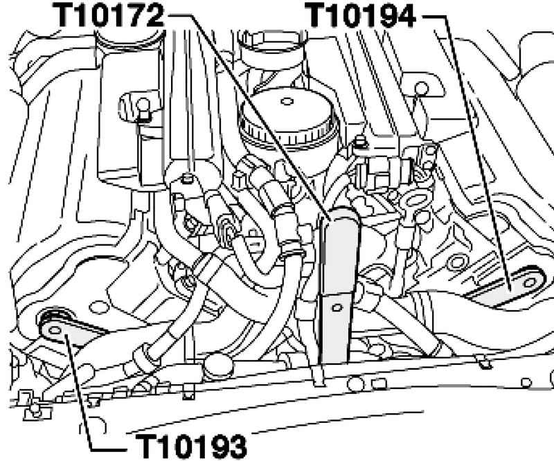
Fig. 2.197. Installation of special devices to control


Rotate the crankshaft by a counter support T10172 slowly in the direction of rotation of the motor shaft until the stopper T10193 camshaft first row of cylinders and stop T10194 camshaft second row of cylinders do not fall into the mounting holes (Fig. 2.197).
Raise the vehicle on a lift.

Combining marks on vibration damper to marking on the adjusting pin
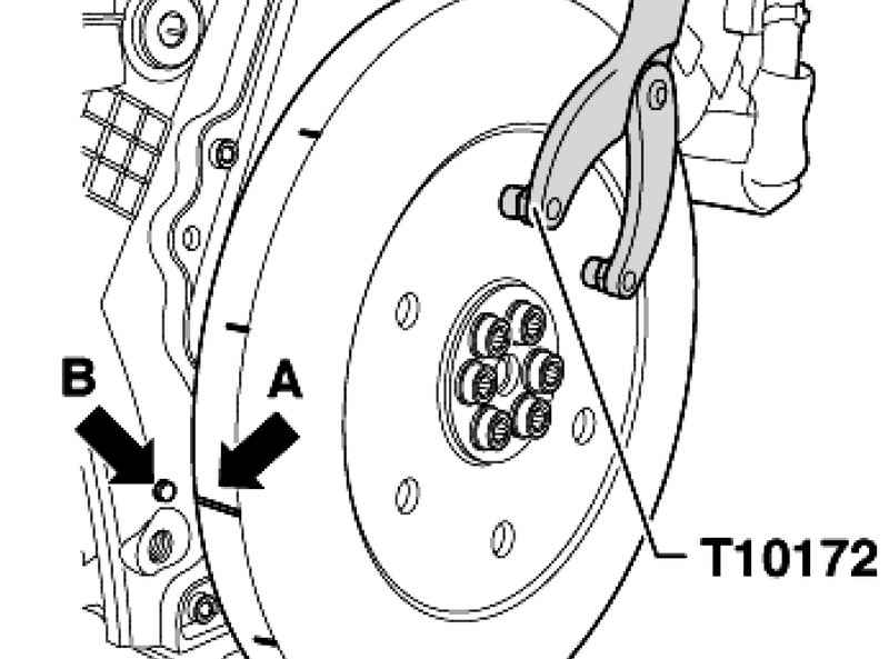
Fig. 2.198. Combining marks on vibration damper to marking on the adjusting pin


Check that the marking arrow A in the vibration damper coincided with the marking on the adjusting pin arrow B (Fig. 2.198).
If the labels do not match, adjust the timing.


« previos page
Removing and installing the camshaft pinion
next page »
The timing

Copyright © 2010 AutoManuals.biz. Trademarks belong to their respective owners. All rights reserved.