printable version printable version
Repair of cylinder heads
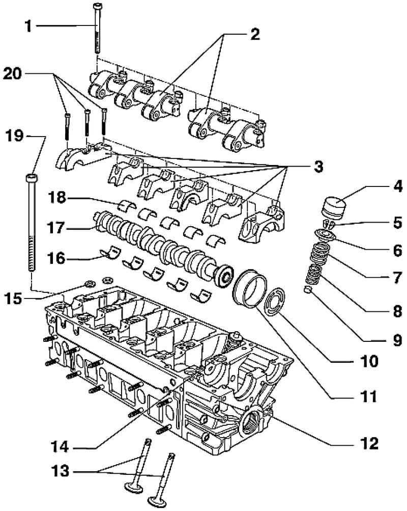
| Fig. 2.207. The components of the valve mechanism 1 - a bolt 20 Nm + to tighten on 1/4. (90 ?°); 2 - axis roller levers; 3 - a cover of the bearing; 4 - bucket tappets; 5 - conical biscuit; 6 - plate valve spring; 7 - External valve spring; 8 - internal valve spring; 9 - the valve stem seals; 10 - a washer with a diamond-coated; 11 - the plug; 12 - cylinder head; 13 - valve; 14 - unit injector; 15 - washer; 16 - bearing; 17 - camshaft; 18 - bearing; 19 - a bolt of the cylinder head; 20 - a bolt 8 Nm + to tighten on 1/4. (90 ?°)
|
Checking the position of pistons in the top dead center Measure the piston protrusion in the conditions of the SRT impossible. The connection of the cylinder head with an aluminum cylinder block is carried out on the principle of an anchor with anchor bolts. Thus it is achieved a compression cylinder, which can not be achieved when dismantled cylinder head. For this reason, when replacing the cylinder head gasket is necessary to install a new cylinder head gasket with an identical index marks.
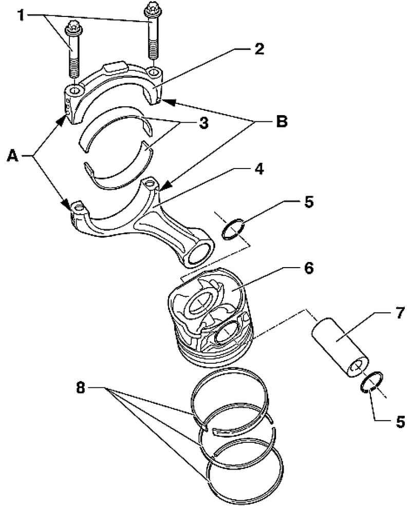
| Fig. 2.208. Piston and connecting rod: 1 - connecting rod bolt 30 Nm + to tighten on 1/4. (90 ?°); 2 - a cover of a rod; 3 - insert bearings; 4 - the connecting rod; 5 - a lock ring; 6 - piston; 7 - piston pin; 8 - piston rings
|
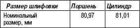
Dimensions of pistons and cylinders
NOTE Repair sizes is not specified. |
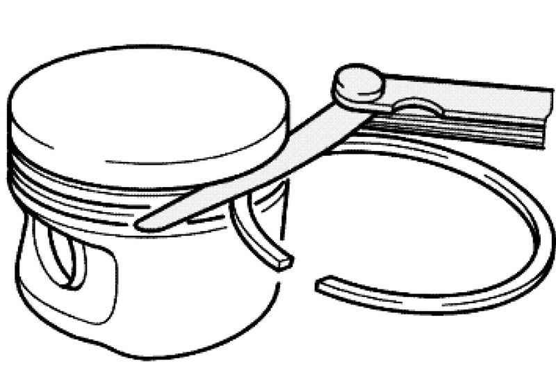
Checking the thermal gap of piston rings
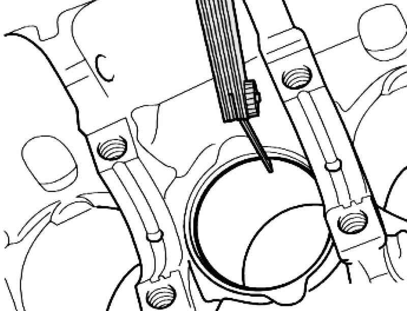
| Fig. 2.209. Checking the thermal gap of piston rings
|
Will drive the piston ring from the top, at right angles to the cylinder wall to the bottom of the cylinder bore at a distance of about 15 mm from its end (Fig. 2.209).
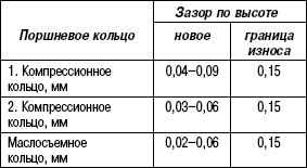
Checking piston ring gap height
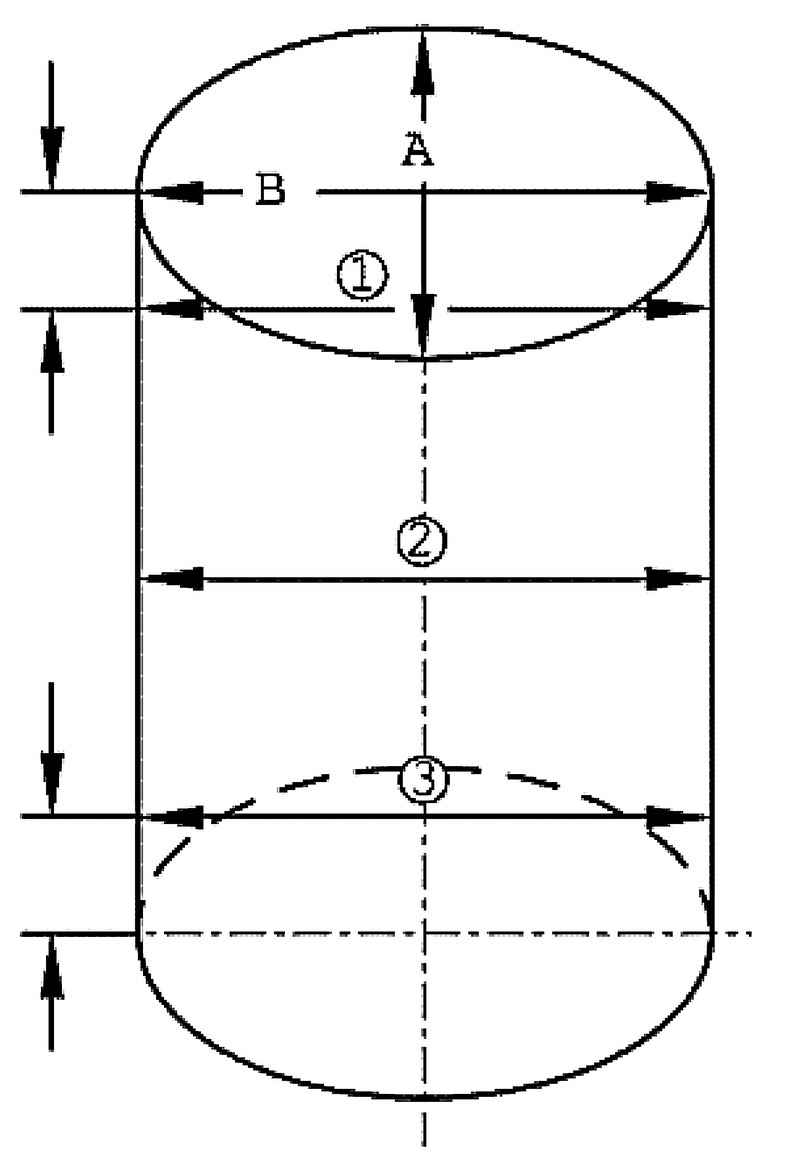
Check the diameter of the cylinder
Measure in three places a cross A cross and longitudinal distance B (Fig. 2.211). The maximum permissible deviation from the nominal size: 0.05 mm. Piston: mounting position and belonging to the piston / cylinder. At the bottom of the piston shall be marked: - Pistons 1-5 for a number of cylinders 1; - Pistons 6-10 for a number of cylinders 2. Location: arrow at the bottom of the piston shows on the suction side.
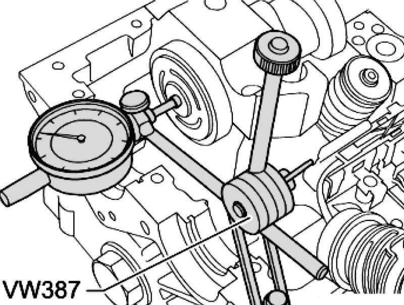
Checking the axial displacement of the camshaft
| Fig. 2.212. Checking the axial displacement of the camshaft
|
Check when dismantled bucket tappets and caps bearing set (Fig. 2.212). The first row of cylinders: - Set bearing caps 2, 4 and 6 The second row of cylinders: - Set bearing caps 9, 11, and 13 Wear limit: max. 0.15 mm Apply sealant to the sealing surfaces of the outer bearing cap.
The order of execution of works
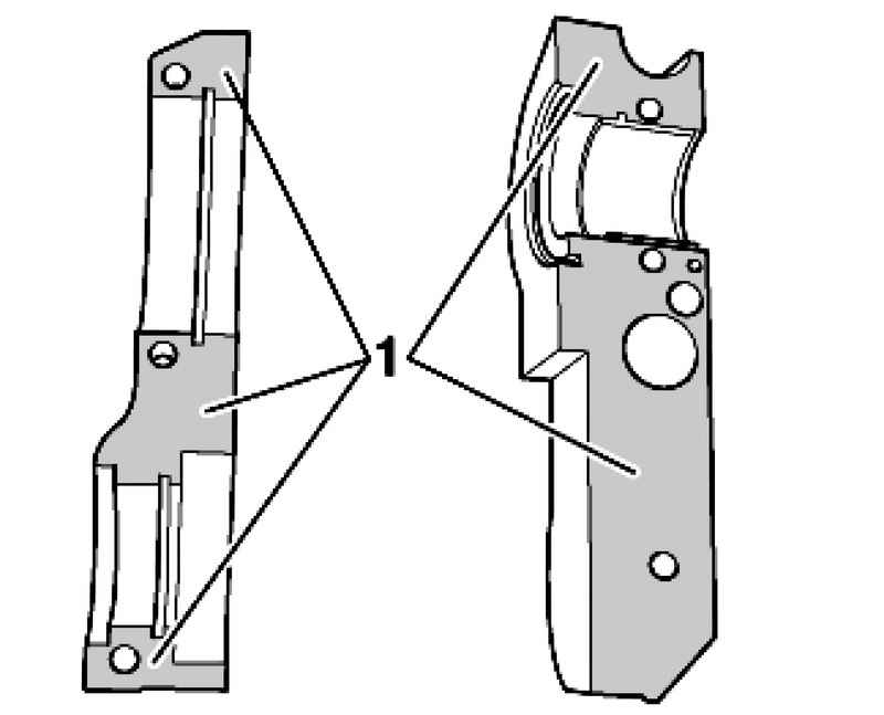
Apply sealant AMV 176 501 on the surface of a thin uniform layer 1 (Fig. 2.213). The first row of cylinders: Apply sealant - AMV 176 501 on the seating surfaces of bearing caps 1 and 7 The second row of cylinders: Apply sealant AMV 176 501 on the seating surfaces of bearing caps 8 and 14
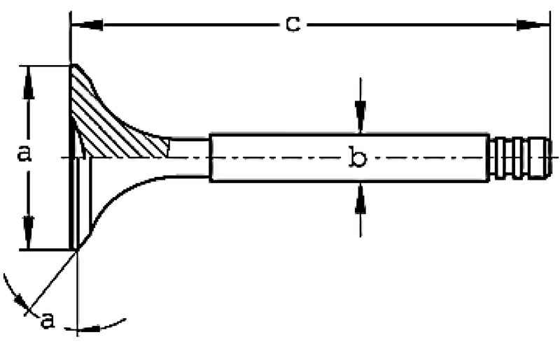
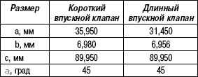
Valve sizes
NOTE Valves prohibited handle. It allowed only lapping. |
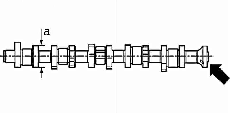
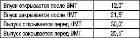
Marking camshaft (timing) The valve cam base circle: a = mm ZH52,8
Markings applied in the form of letters and numbers stamped on the end face of the drive end of a camshaft (Fig. 2.215). Side Drive The first row of cylinders: 07Z G. The second row of cylinders: 07Z H.
Valve timing at 1 mm valve during
Processing valve seat
NOTE When repairing engines with leaky valve handle or replace the valve seats and valve insufficiency. Particularly in engines with long service life, check the valve guides for wear. Valve seats should be treated only as to achieve the perfect type of work surface. Before treatment should calculate the maximum allowance for processing. If you exceed the allowance for processing may be impaired function of the hydraulic control valve clearance (lash), which would entail the replacement of the cylinder head. |
Expect the maximum allowance for processing as follows: - Insert the valve into the guide and press it firmly to the saddle;
NOTE If the valve is replaced during repair, then the measurements use a new valve. |
| Fig. 2.216. A distance between the end of the valve stem and the upper edge of the cylinder head
|
- Measure the distance A between the end of the valve stem and upper edge of the cylinder head (Fig. 2.216); - Calculate the maximum allowance for processing on the basis of the measured distance A and the minimum size. Minimum size: The inlet valve - 43.4 mm Exhaust valve - 43.2 mm Measured distance minus minimum size = maximum allowance for processing. Example: Measured distance - 44.1 mm Minimum size - 43.4 mm The maximum allowable allowance for processing 44,1-43,4 = 0,7 mm
Processing inlet valve seat
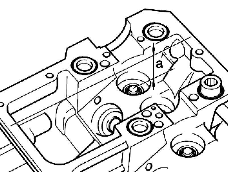
| Fig. 2.217. The processing circuit inlet valve seat
|
a - ZH35,7 mm b - 1,6 mm 45 ?° - angle of the support surface of the valve
NOTE Milling at an angle of 30 ?° valve seat is necessary because of the ratio of inlet flow. |
Processing saddle valve
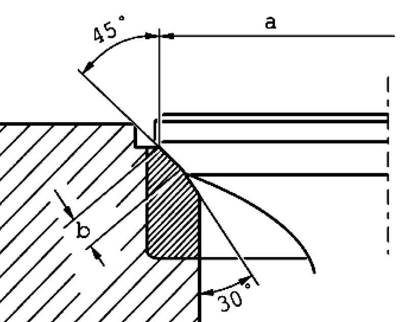
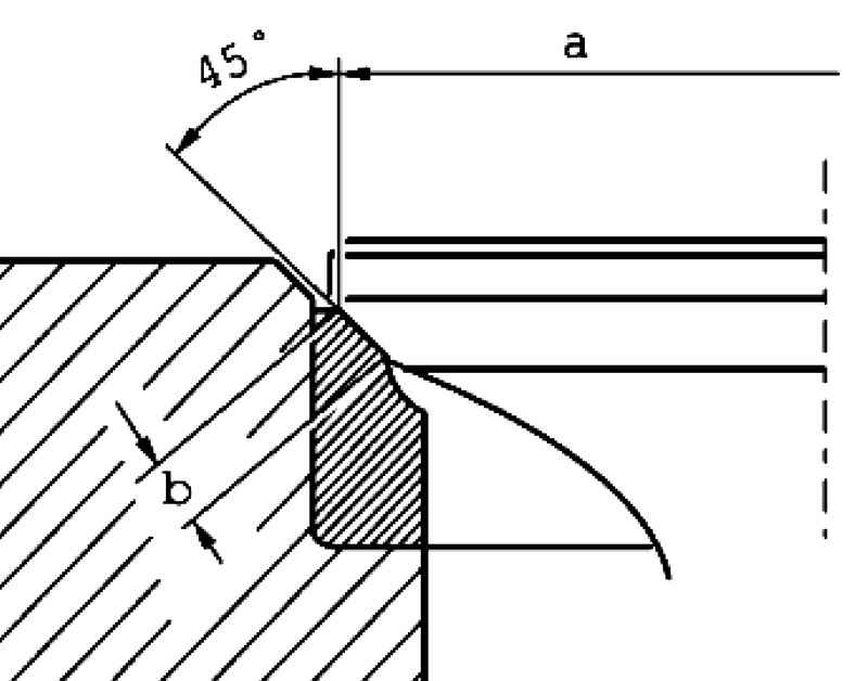
| Fig. 2.218. The processing circuit of the exhaust valve seat
|
a - ZH31,4 mm b - 2,7 mm 45 ?° - angle of the support surface of the valve
Checking the valve guides Insert the new valve into the guide sleeve. The end of the valve stem must overlap the guide sleeve. Due to the different diameter shaft using only intake valve guide sleeve of the intake valve and the exhaust valve guide sleeve exhaust valve.
Wear limit: max. 1.3 mm. If the backlash exceeds the limit values of wear - replace the cylinder head.
Replacing the valve stem seals (if installed cylinder head) Remove the camshaft. Remove the poppet valve lifters and put them face down. Do not reverse bucket tappets. Move the piston of the corresponding cylinder to TDC.
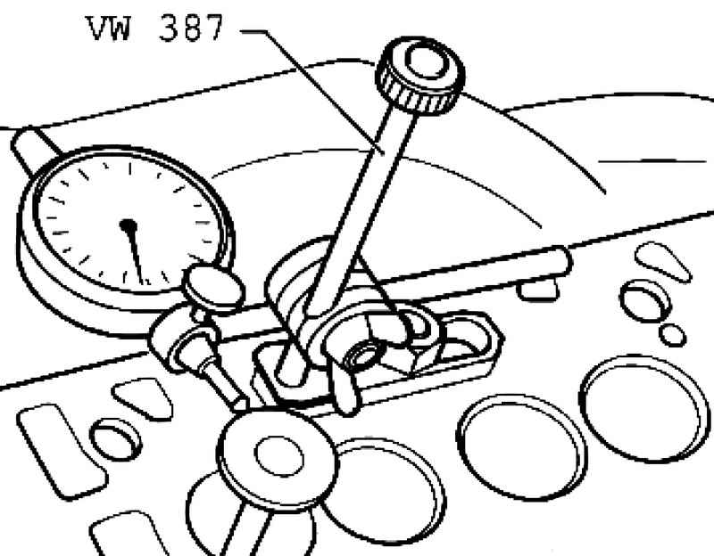
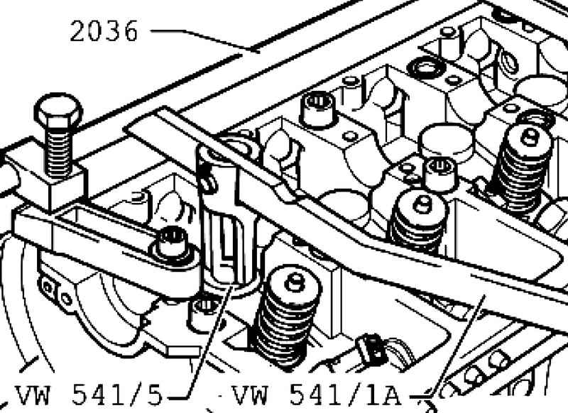
| Fig. 2.220. Installation devices for removing valve springs
|
Install the mounting device for the valves 2036 and establish a support with spacers (Fig. 2.220). Remove the valve springs with a lever for removing valve springs VW 541/1 A and mandrel VW 541/5.
NOTE Wherein the valve rest on the bottom of the piston. |
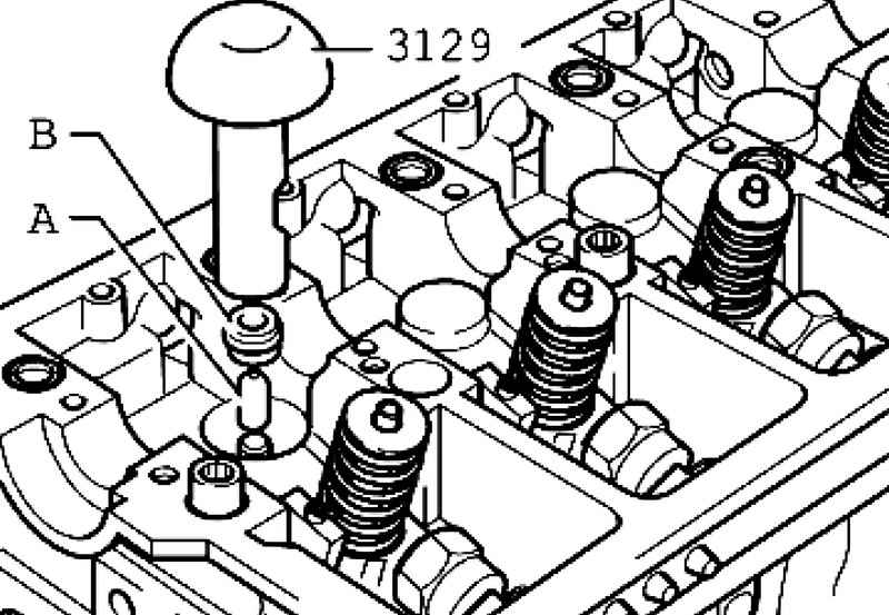
Setting
Put on appropriate valve stem included in the repair kit plastic cover A (Fig. 2.222). This helps to avoid damage to the new valve stem seal B. Install the new valve stem seal in the mandrel 3129. Grease the sealing lips of the valve stem and gently replace the valve guide. Install the camshaft.
|