printable version printable version
Removing and installing the camshaft pinion
NOTE After each removal of gear in the assembly should be inspected and, if necessary, adjust the position of the piston pump nozzles. |
NOTE Described below and depicted workflow components are provided to the first row of cylinders. Differences from the second row of cylinders are insignificant and do not require description. |
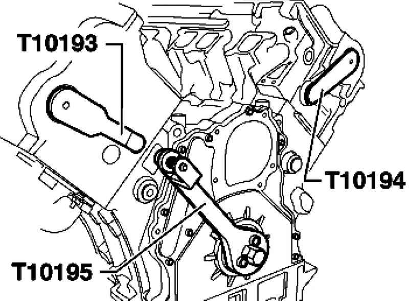
Withdrawal Remove the engine and transmission. Remove the valve inlet hose and crankcase ventilation resp. cylinder. Remove the soundproof cover and cylinder head cover corresponding cylinder head. Check countertops axle rocker arms for signs of wear or damage. Disconnect the water pipe under the tandem and the fuel pump. Remove the vibration damper. Use a counter support T10172 bolt T10172 / 1. Screw the stopper T10195 crankshaft to the end of the crankshaft. At the same care that the dowel pin.
| Fig. 2.185. Installation of stops and counter-supports
|
Then carefully rotate the crankshaft until crankshaft stop lug T10195 will not get into the calibration hole (Fig. 2.185). Remove the corresponding pump. 1st row of cylinders: a tandem pump. 2nd row of cylinders: a fuel pump. Remove the oil feed line to the turbocharger.
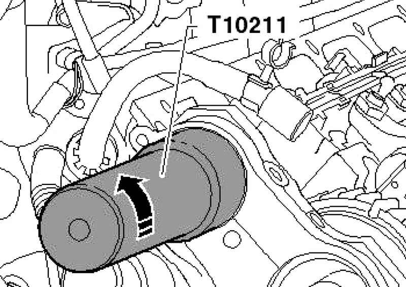
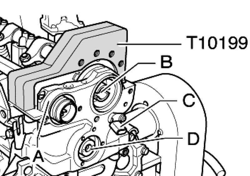
Insert the key T10211, as shown in Figure 2.186, and loosen the adapter ring of the central connector unit injectors. Remove the Hall sensor G40-C (only for the 1st row of cylinders). Remove the outer bearing cap A, set the jig T10199 gear on the camshaft and tighten the device with 40 N ?· m.
Loosen the fixing bolts in the camshaft gear using the front and unscrew the nozzle T10198 with the drive mechanism of a tandem pump (Fig. 2.187). Loosen the screws jig T10199 and remove it.
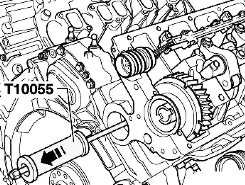
Remove the compensation piston axis compensation The removable lining (Fig. 2.188). Remove from puller T10055 removable head injectors.
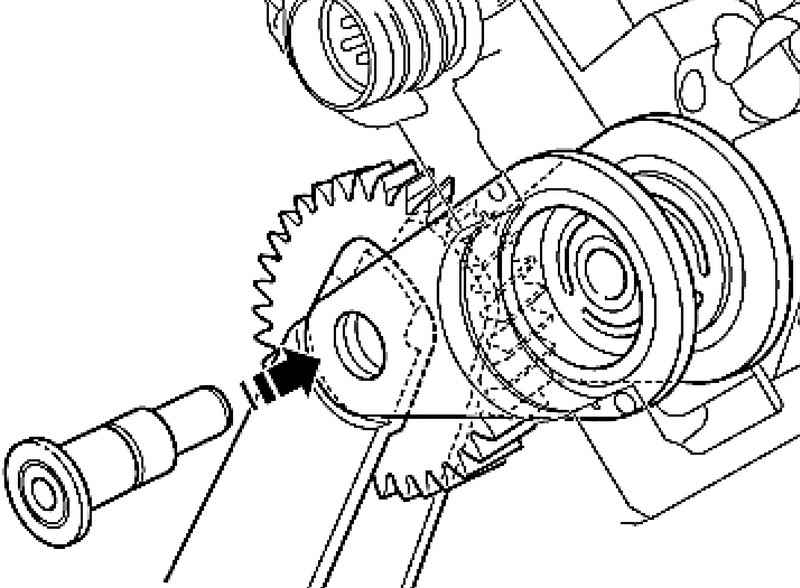
Screw the puller T10055 as shown in Figure 2.189, the guide axis, gently tapping, remove the axis in the direction of the arrow.
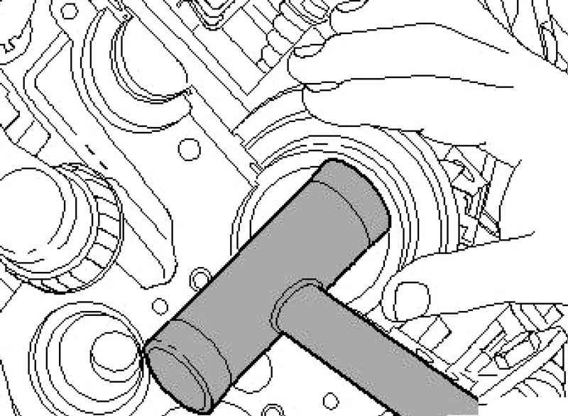
| Fig. 2.190. Removing the outer lining of the compensation
|
Remove the outside (on the side of the PPC) compensation pad out of its slot. If necessary, it stronte light plastic mallet (Fig. 2.190). Remove the camshaft gears. Now remove the pinion and the internal compensation compensation cover.
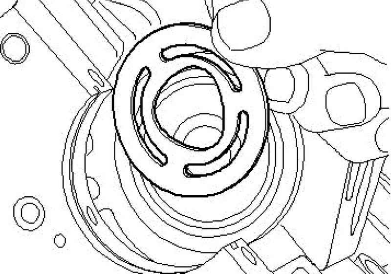
Remove the diamond from the console of a cam washer (Fig. 2.191).
Setting Clean the contact surface of the bearing cap from the remnants of sealant. Lubricate the guide surfaces of the compensation sleeve lining.
NOTE When the presence of a significant break-in or deposit on the guide surface of the sleeves of their compensation pads must be replaced. |
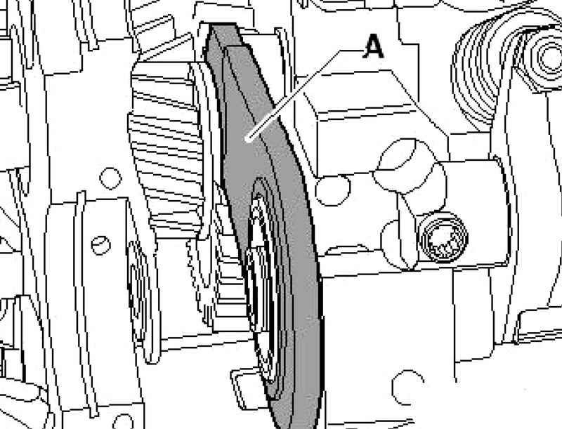
| Fig. 2.192. Installing an internal compensation pad
|
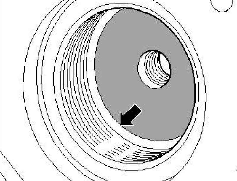
Hook inside (on the side of the engine) compensation cover A first at the bottom (if necessary, to send a finger through the hole in the expansion piston) and finally at the top of the slide bush (Fig. 2.192). Install a new washer on the diamond console camshaft.
| Fig. 2.193. The direction of installation of the compensation gears
|
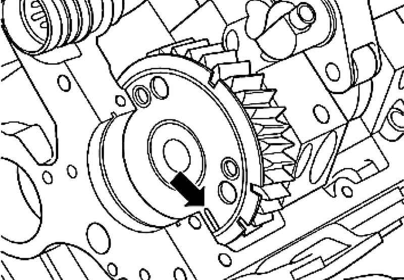
Bring lower compensation pad (on the transmission) position and set the compensation gear in phase (Fig. 2.193) in the direction of the checkpoint.
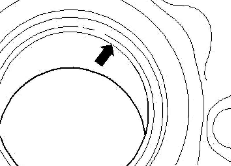
Installation rotate camshaft gear so that the labeling (Fig. 2.194) on the drive gear coincides with the upper edge of the seat surface. Fix the unit by gently inserting the (possible with a uniform force) locking arm axis.
ATTENTION There is a danger that the lining of the unit gears can slide to one side and not dressed to guide the axis or axes to happen when you slide bias. |
Insert the guide sleeve in the compensation cover on the side of the checkpoint. Carefully remove the lock axis. At the same time, make sure that the covers have adjusted compensation remained in the correct position. Install the trim compensation on the side of the inscription to the PPC PPC. If you want to prop up its light plastic mallet on the guide sleeve. Check the landing pad compensation finger through the hole compensating piston.
Compensation gear should be centered so that the four holes on the lining and on the gear coincide with each other (Fig. 2.195).
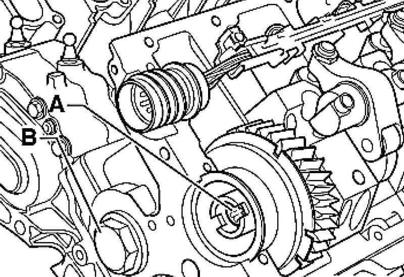
Lubricate the axis of the guide, then slide her hand, uniformly applying force. Proper planting latch pin can be identified by a noticeable gap in the hole in the cylinder head (Fig. 2.196). Install the drive tandem or fuel pump. Install the bearing cap is flush with the edge of the cylinder head on the sealant AMV 176 501 and secure them. Install the new compensation piston. Set the jig T10199 and tighten a bolt of camshaft sprocket.
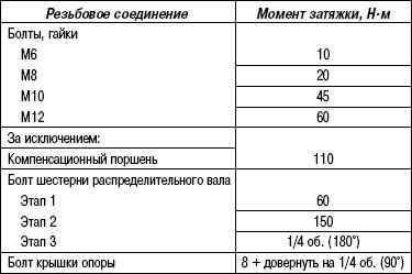
Tightening torques
|