printable version printable version
Removing and installing ramps crankshaft bearings
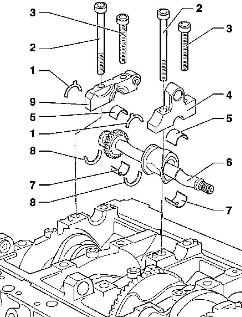
| Fig. 2.168. Blansirny shaft: 1 - an adjusting washer; 2 - bolt main bearing; 3 - a bolt bearing caps; 4 - a cover of support; 5 - insert bearings; 6 - balancer shaft; 7 - insert bearings; 8 - an adjusting washer; 9 - Cover support
|
NOTE Removing the balancer shaft is only possible if the module was previously removed the dispensing mechanism. |
ATTENTION The upper part of the ramp supports connected to the engine crankcase by means of two M8 screws with hexagon socket, which are located between the cylinder head. These compounds are in any case impossible to unwind as a result is not repairable deformation of the cylinder block. |
NOTE For assembly work the engine must be secured by a lock for the engine and gearbox VAS 6095. |
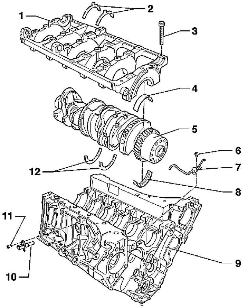
| Fig. 2.169. Crankshaft: 1 - ramp crankshaft bearings; 2 - an adjusting washer; 3 - bolt main bearing; 4 - insert bearings; 5 - the crankshaft; 6 - bolt8 N ??? m; 7 - Oil injection nozzle; 8 - insert bearings; 9 - the cylinder block; 10 - the gauge of engine speed G28; 11 - a bolt to 10 N ??? m; 12 - shim
|
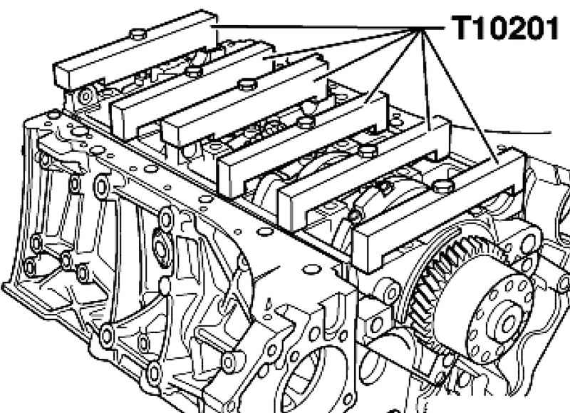
Set the jig T10201 at the bottom of the ramp crankshaft bearings as shown in figure 2.170. Tighten bolts jig T10201 with a torque of 20 Nm. Remove the bottom of the ramp engine mounts.
Setting Set the jig T10201 at the bottom of the ramp crankshaft bearings and tighten bolts to 20 Nm. Make sure that all bearings liners are properly installed in the support brackets. Pay attention to the shims. Carefully place the lower part of the ramp crankshaft bearings in the engine block.
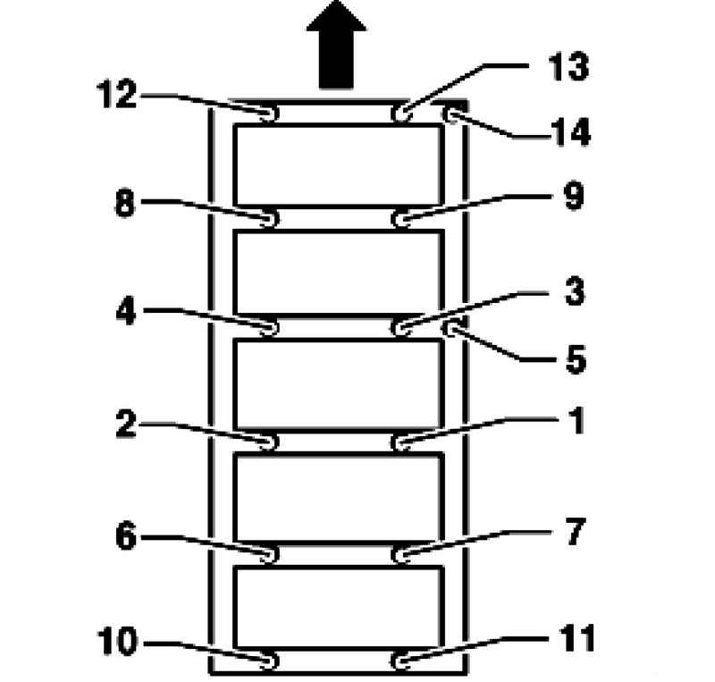
| Fig. 2.171. Order of a tightening of bolts of main bearing
|
Tighten main bearing screws in three stages in the sequence (Fig. 2.171) shows the direction of motion). 1 - Apply the torque wrench: - Stage 1 = 35 Nm; - Phase 2 = 65 Nm. 2 - Next, turn the key in the usual: - Phase III = tighten 1/2 turn (180 ?°).
|