printable version printable version
Removing and installing door lock
Frame mounted units consist of the mounting frame and the frame of the glass. The frame mounted units fixed windows, door lock and speaker. The door lock can be removed only with a frame mounted units.
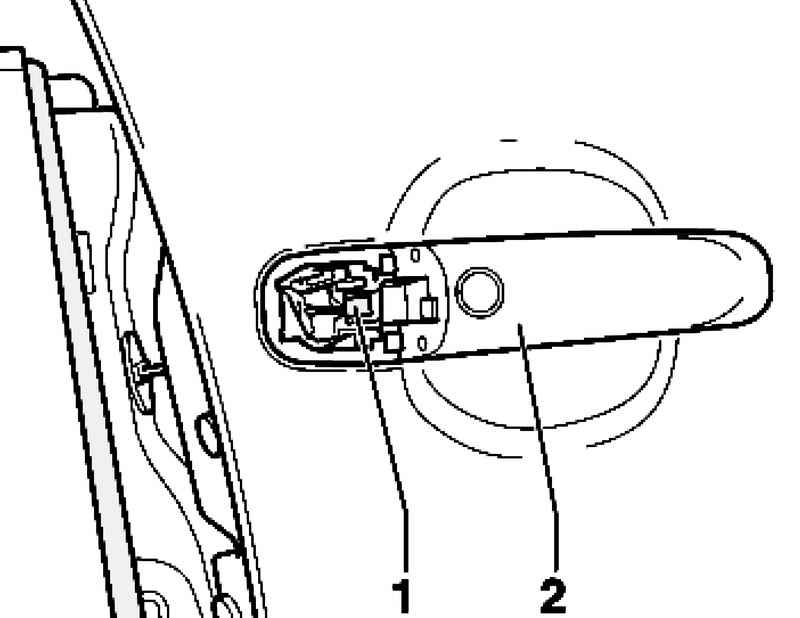
Withdrawal Remove the front door trim. Removing the housing of the lock cylinder.
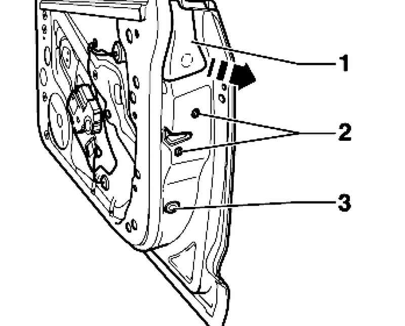
Unscrew bolts 1 and 3 of the frame window. Torque: 20 Nm. 2 Remove the screws from the door lock. Torque: 20 Nm. Pry the caps 1 and 5.
Torque: 20 Nm. Remove the screws from the door lock. Torque: 20 Nm. 3 Remove the bellow from the front A and disconnect plugs. Spend casing and plugs through the hole in the door cavity.
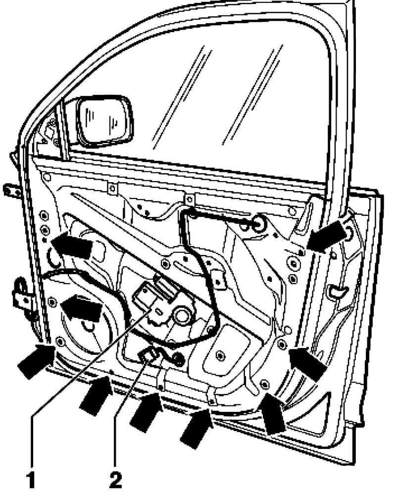
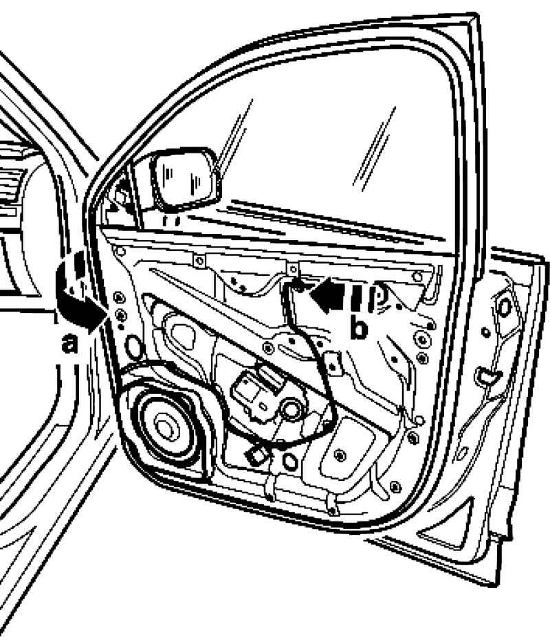
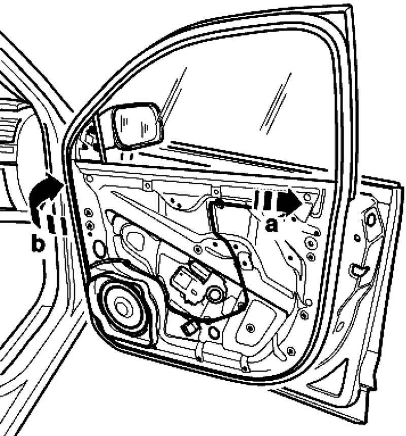
2 Remove the plug from the power window motor 2 and run it through the hole in the mounting frame (Fig. 8.34). Remove the bolts. Torque: 8 Nm. Gently pull the front of the frame mounted units from the outer door panel a. Please note that the cables are not stretched.
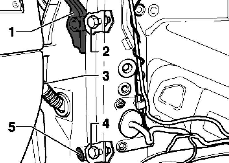
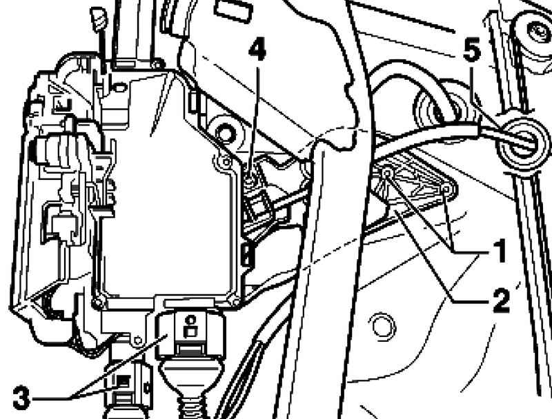
Pull frame mounted units to the side door hinges from the outside of the door panel b (Fig. 8.35). At the same time, make sure that the door lock is not caught on the outer door panel. Drill out the two rivets 1.
Disconnect the plugs 3 and squeeze the rubber sleeve 5 of a frame mounted units (Fig. 8.36). Bracket is secured to the door lock by means of the rivets 4 and the retainer.
NOTE Bracket is not included with the door lock. Each removed his replacement is needed. |
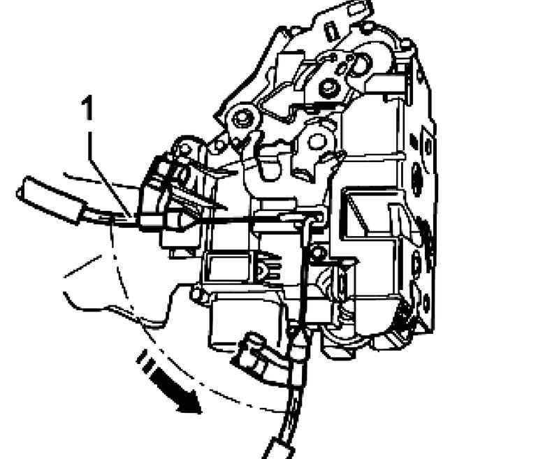
Disconnect the flexible cable 1 from the door lock (Fig. 8.37). Turn the nipple of the flexible cable 90 ?° and remove it from the hinges. Installation of the door lock in reverse order.
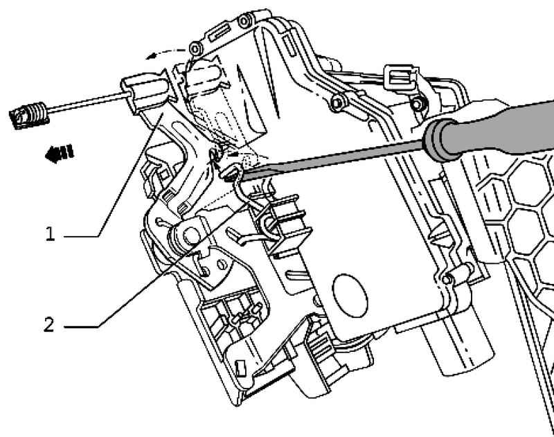
Setting Pull the lever 1 in direction.
Tighten with a screwdriver mounted on the door lock spring 2 in the direction of the arrow and hook the lock lever in the spring (Fig. 8.38).
NOTE Hanging lever, you fix the lock. Thus, it is possible to avoid possible "wrong" fixing the flexible cable. |
Insert frame mounted units in the door. Insert frame mounted units on the hinge side in the outer door panel a. At the same time make sure that the door lock freely entered into a niche in the outer door panel.
Press frame mounted units in front of the door to the outer panel b (Fig. 8.39). Loosely all screws and tighten them. Torque: 8 Nm. Please note that the cable has been properly carried out between the outer door panel and the frame glass.
NOTE When clamping the cable between the outer door panel and the frame of the glass may be damaged, resulting in malfunction of electrical components built into the door. |
Loosely all screws and tighten them. Torque: 8 Nm. Check whether all three elements are tightened regulation. Loosely all four screws - arrows - glass frame. Place the frame window height and angle exactly in accordance with the contours of the vehicle. First, tighten the upper bolt on the side hinges. Then tighten the bolt in the other three elements of the regulation. Further installation in reverse order. Finally, check the operation of the door lock.
|