add to favorites contacts sitemap
REPAIR MAINTENANCE OPERATION OF MOTOR VEHICLES
Volkswagen Touareg (from 2003 to 2006, the year of issue)

general info. full specifications. diagnostics. hints. tips. tricks
Volkswagen Touareg
Home
 
Volkswagen
Touareg
Operation and maintenance of car
Engine
Transmission
-speed automatic transmission 09D
Check the torque converter
Draining fluid from the torque converter
Install the torque converter
Repair of the drive gear
Removing and installing selector lever
Check and adjust thrust selector
Removing and installing selector rods
Removal and installation of overlays
Removal and installation frame
Removing and installing selector lever lock solenoid N110
Removing and installing selector switch (the lever is locked in position ?�P?�) F319
Removal and installation of the drive gear
Removing and installing the gearbox, cars with diesel engine R5
Removing and installing the gearbox, cars with petrol engines V6 and V8, turbodiesels V6 TDI, V10 TDI and W12 engine petrol
Tightening torques
Removal and installation of lines and ATF cooler
Removing and installing control unit of an automatic transmission J217
Replacement of a sealing ring of a secondary shaft
Removing and installing oil pan
Removing and installing oil strainer
Removal and installation of the hydraulic pressure sensor for the automatic transmission 1 and G193 for hydraulic pressure sensor 2 G194 AKP
Removal and installation of the slide valve box
Removal, installation and adjustment of the multi-function switch F125
Manual transmission and transfer case 08D E473
The propeller shaft
Drive Train
Tables
Chassis
Steering Gear
Brakes
Onboard electric
Body
diagrams


Hit Counter by Digits


print page printable version

Removal and installation frame


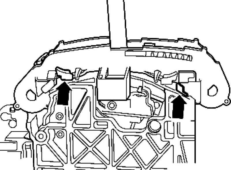
Withdrawal
Remove the cover.

Catches frame
Fig. 3.16. Catches frame


Pull the latches on the left and right side out and pull the frame up (Fig. 3.16).

Setting
Installation is carried out in reverse order.
Install the patch.
Switching the selector in the absence of power from position ?�P?� - emergency release.

Fitting screwdriver
Fig. 3.17. Fitting screwdriver


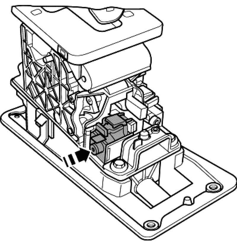
Click on the top of the magnet core by means of a long, thin screwdriver in the direction of the arrow (Fig. 3.17).
It is not necessary to remove the handle.
Removing and installing selector lever lock solenoid in position ?�P?� N380.

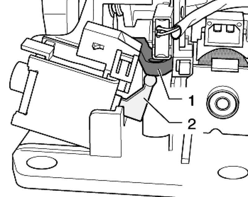
Withdrawal
Remove the drive gear.
Unlock and disconnect plug.

The locking lever gear
Fig. 3.18. The locking lever gear


Unlock the solenoid in mounting and pull up the outside of the locking lever 1 and the drive gear (Fig. 3.18).

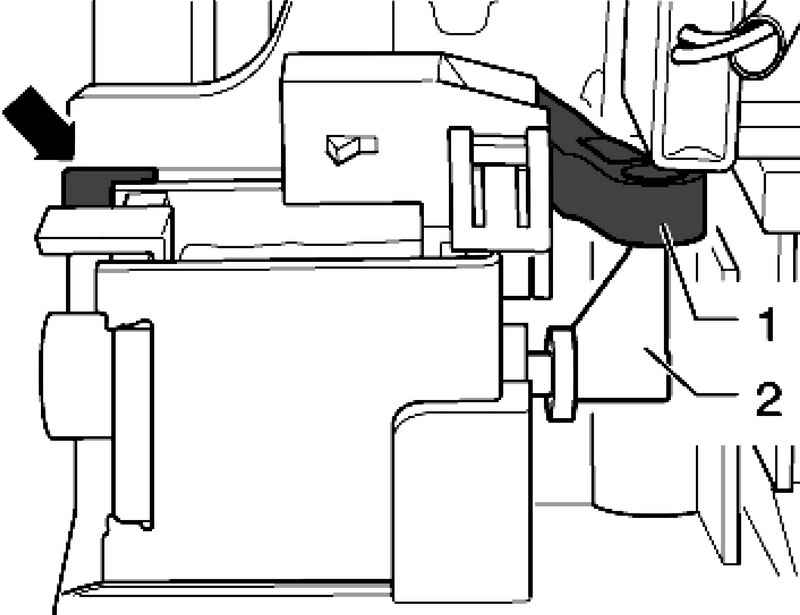
Setting
Put the lever of the electromagnet 2 vertically.
Install the solenoid at a slight angle to mount the drive gear.
Connect the lever 2 with a locking lever 1 (Fig. 3.18).
Slide the solenoid to lock the drive in gear until it locks in its bracket arrow.

Installing rachaga
Fig. 3.19. Installing rachaga


Check that the solenoid is mounted in the fixture against the stop and the lever 2 is in engagement with the locking arm 1 (Fig. 3.19).


« previos page
Removal and installation of overlays
next page »
Removing and installing selector lever lock solenoid N110

Copyright © 2010 AutoManuals.biz. Trademarks belong to their respective owners. All rights reserved.