printable version printable version
Removing and installing the gearbox, cars with diesel engine R5
Short description In these vehicles can be removed individually for transmission down. The engine is mounted in the vehicle. In the Touareg with any versions of the engine is recommended before removing the power unit to dismantle the lower bolts connection engine / gearbox. If possible, pre-set torque converter. These board functions as when removing, and when installing the transmission.
Withdrawal Remove the engine cover.
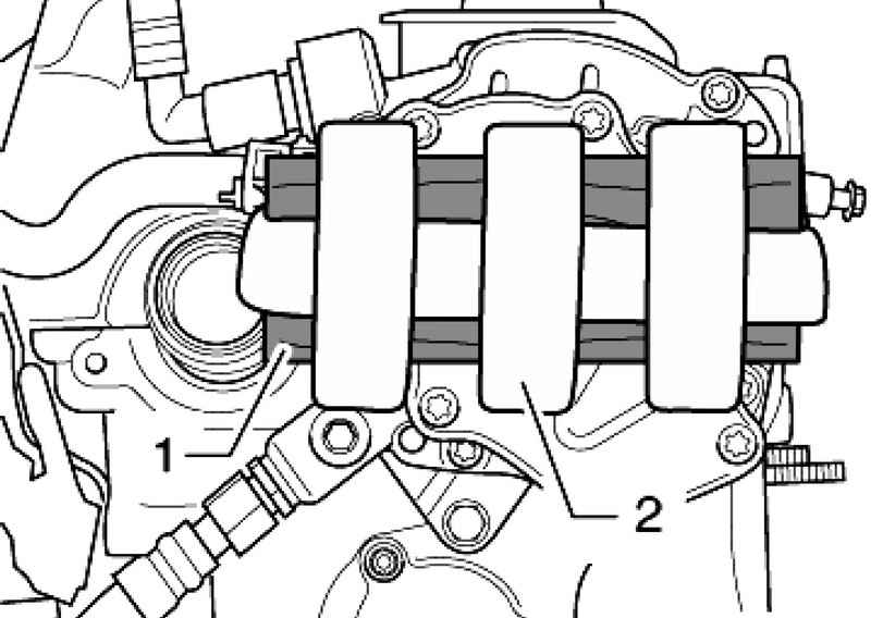
NOTE Figure 3.28 shows a tandem pump bottom at the removed engine. |
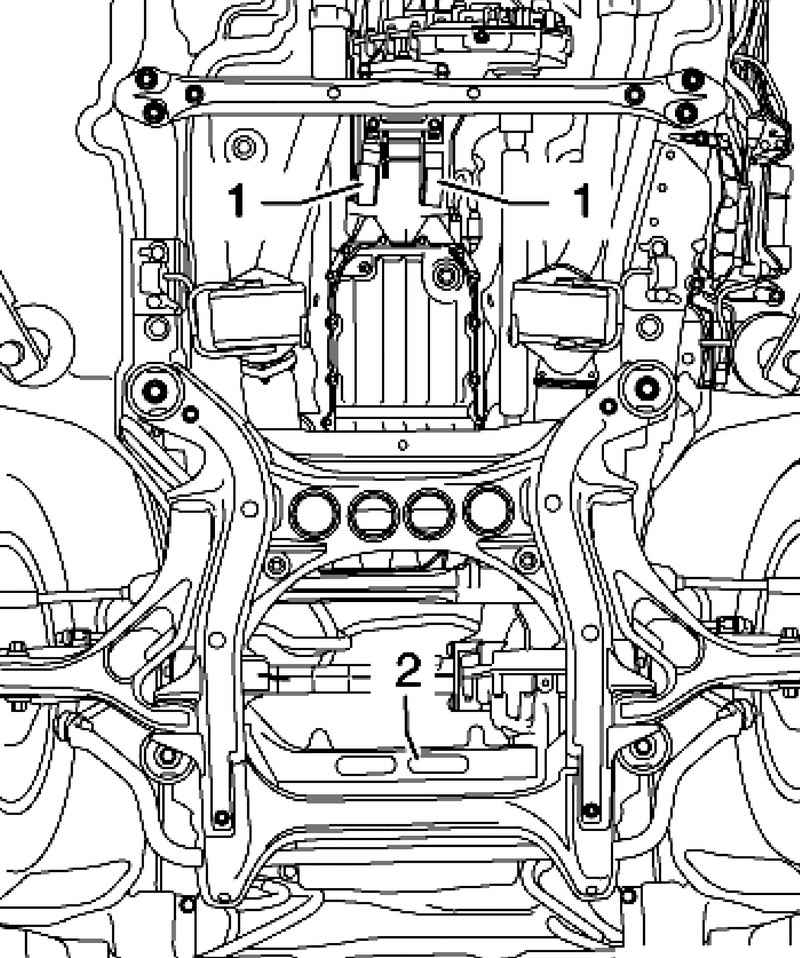
Secure wooden shim 20 mm 1 with adhesive tape 2 as shown on the pump of the tandem type (Fig. 3.28). If too thin wooden or wooden lining pad is not used, with a further dismantling of the gearbox can lie down on the stretcher, and the transmission can not be removed.
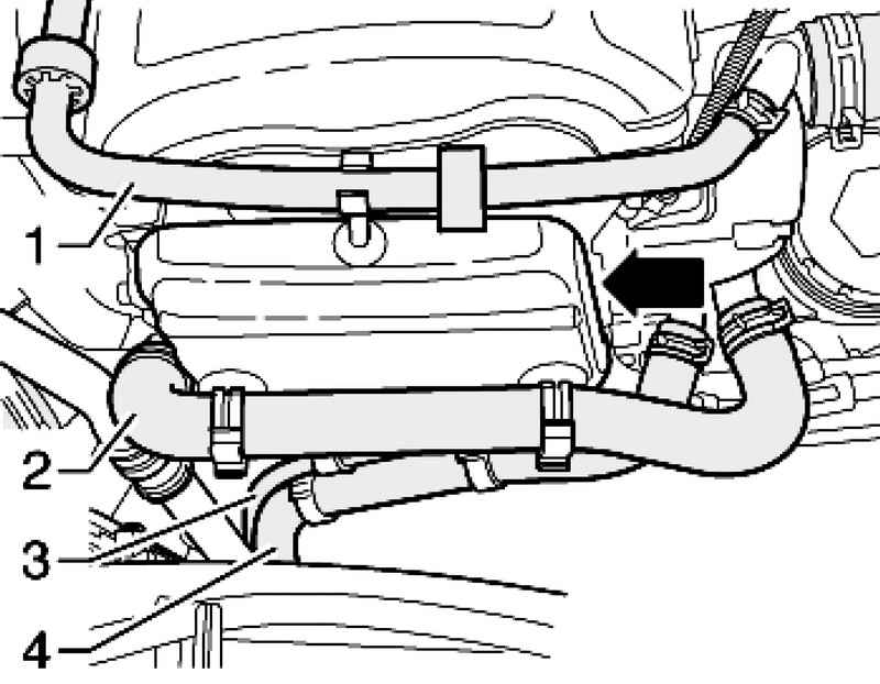
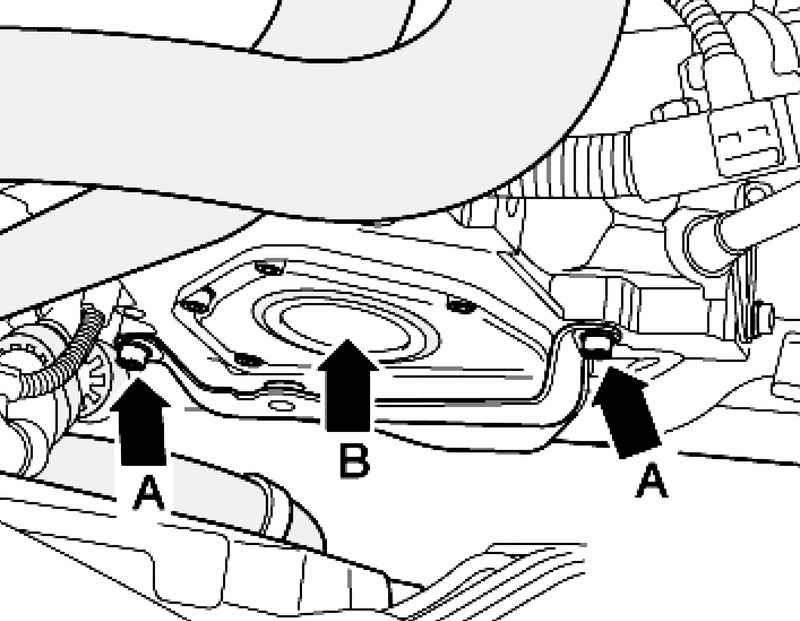
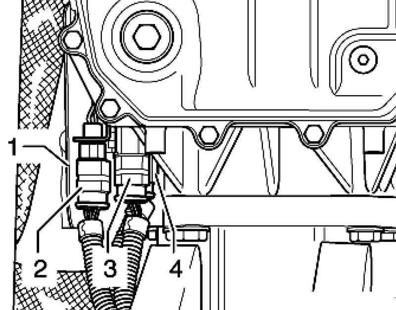
Remove the coolant hoses 1-4 with soundproofing on the front side of the engine (Fig. 3.29). Remove noise insulation (3 screws). Remove the bolts A and remove the holder soundproofing.
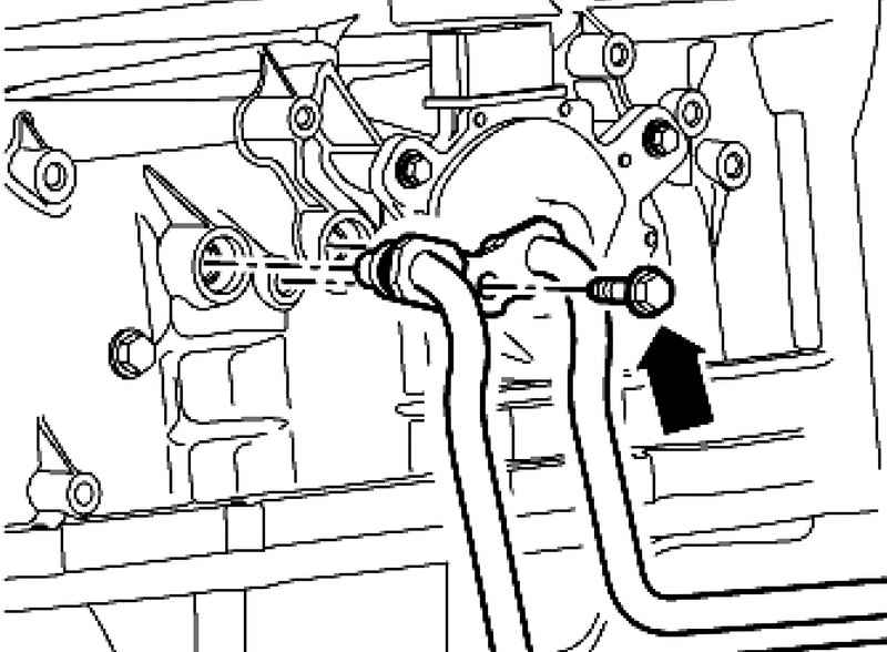
Remove the sealing cap B using puller 10-221 with sealing flange (Fig. 3.30).
You should always observe the sequence off of the battery. Turn off the mass of the battery terminal. with the ignition off. Completely remove the noise insulation of the engine / transmission.
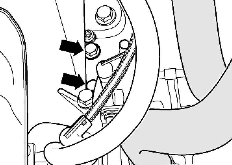
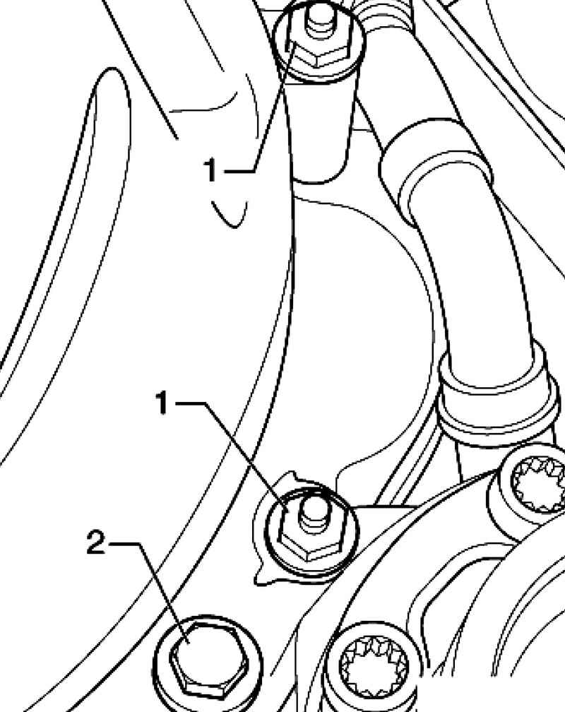
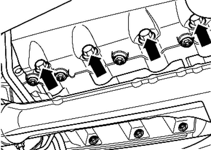
Unscrew the bolts of the coolant hoses on the right engine mount (Fig. 3.33).
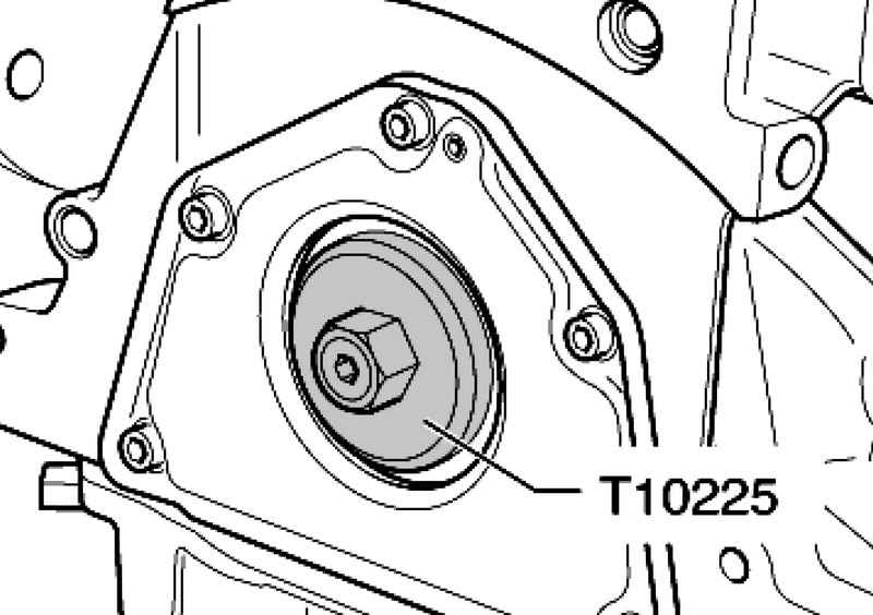
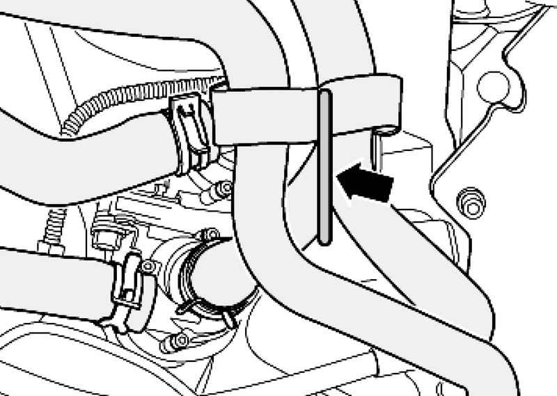
Pull coolant hoses, as shown, up and fix, for example by means of welding wires to the right engine mount (Fig. 3.34). Remove the torque converter bolts / drive plate (6 pcs.). Rotate the torque converter / slave drive via the crankshaft of the engine via the nozzle T10225 1-3 turn (120 ?°) in the rotation direction of the motor shaft (fig. 3.31).
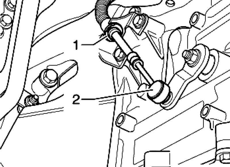
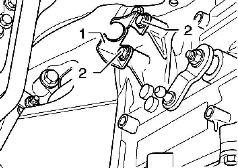
Remove the lock washer 1 and 2 of the selector rod hand with the shift lever (Fig. 3.11).
Close the tube and the hole ATF gearbox using clean plugs.
Remove the bolt holder tubes ATF to the gearbox (Fig. 3.37).
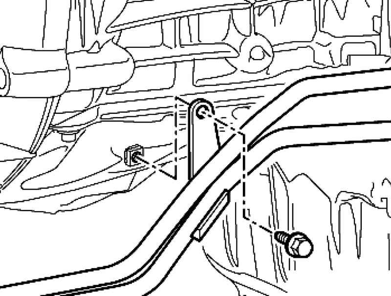
Remove the retaining bolt of the engine / gearbox before lowering the power unit (Fig. 3.38). Removing the bolt in the box can not be lowered due to lack of space. Remove the transfer case. Remove the front exhaust pipe with catalytic converter.
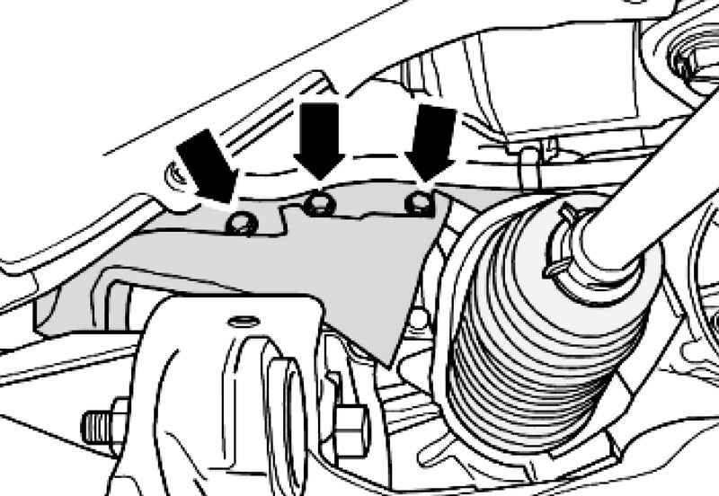
Remove the screen 1, unlock and disconnect plug connections 2-4 (Fig. 3.40). Lower the gearbox a bit as follows.
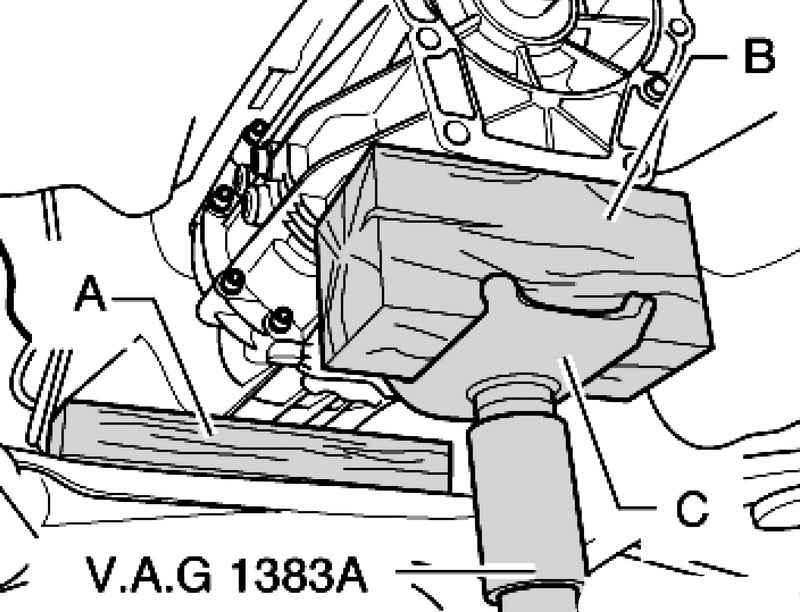
Place the tip of Jacks With the rack for the engine and gearbox VA G 1383 A and put on top of a wooden shim B (Fig. 3.41). Set the rack for the engine and gearbox VA G 1383 A under the gearbox. Lift the gearbox so that it was possible to remove the holding device VW 785/1 B (used for removing and installing transfer case) from the gearbox. Then put the wooden lining and the thickness of about 50 mm between the gearbox and subframe. Make sure that the wood was not under seal tubes ATF. Lower and set aside a rack for the engine and gearbox VAG 1383 A.
| Fig. 3.42. Bolt holder the right front exhaust pipe
|
Loosen the nuts 1 and remove the holder of the right front exhaust pipe 2 to the starter mounting bolts (Fig. 3.42). Starter cable can be left installed. Unscrew bolts 1 and remove the starter from the engine / transmission.
| Fig. 3.43. Bolts starter mounting bolt and engine / transmission
|
Remove the retaining bolt of the engine / gearbox 2 (Fig. 3.43).
| Fig. 3.44. Nuts and bolts of the pipes of the cooling system
|
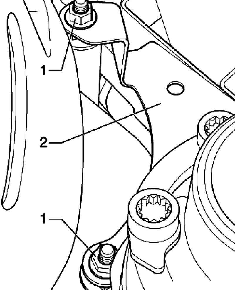
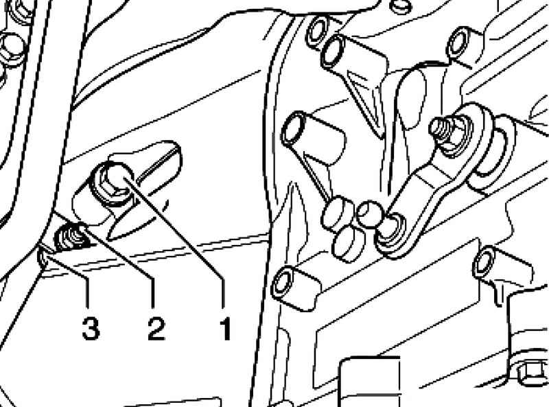
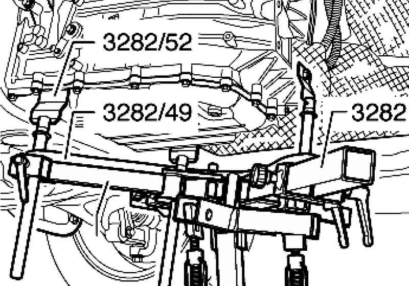
2 Unscrew the nut of the tube cooling system with screws 3 (Fig. 3.44). Remove the bolts connection engine / gearbox 1 and 3. Adjust the stop transmission 3282 for dismantling automatic gearbox ?«09D?» via adjustment plate 3282/49. Install the palm transmission 3282 in the rack for the engine and gearbox VAG 1383 A. The lever arm stop transmission soorientiruyte in accordance with the holes in the adjustment plate. Symbols to indicate the required adjustment plate support parts, the arrow indicates the direction of movement. Set the rack for the engine and gearbox VAG 1383 A, with an emphasis gearbox 3282 under the car.
Secure the rear gearbox emphasis 3282/52 by a screw M10 x 30 (Fig. 3.45).
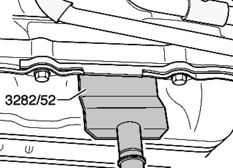
Secure the left and right on the gearbox emphasis 3282/52 under the oil pan (Fig. 3.46). Then, lift the gear box so that you can remove the wooden shim between the gearbox and subframe. When lowering, make sure that the tube to ATF are not pinched between the gearbox and subframe. Carefully lower the gearbox, the engine comes into contact with the wooden lining on the pump tandem and will adhere to the wall. Browse connecting bolts the engine / gearbox.
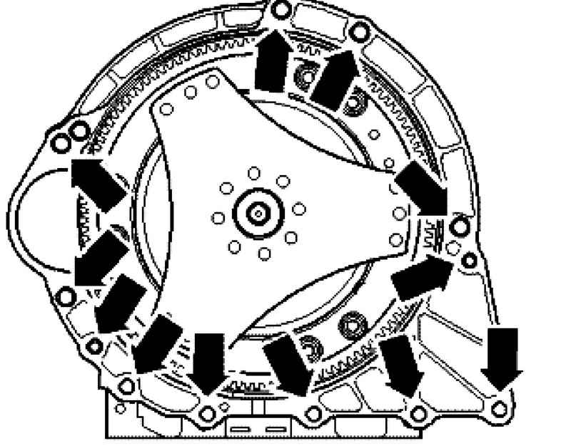
| Fig. 3.47. Bolts of fastening of a transmission to the engine
|
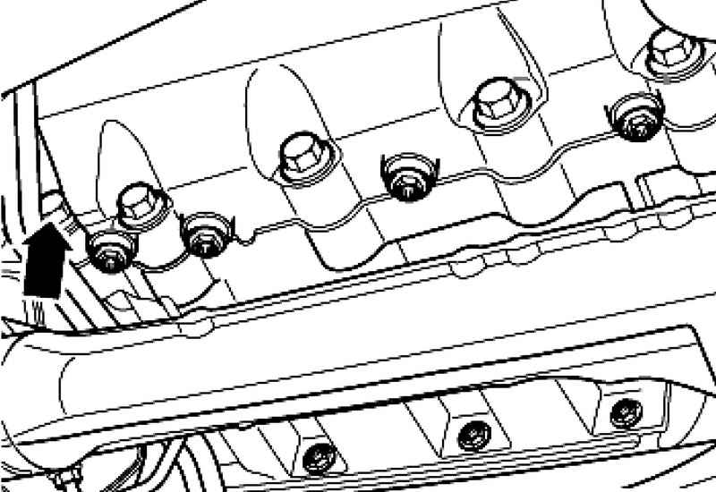
Remove the two bolts connecting the engine / gearbox upper left (Fig. 3.47).
Remove the lower connecting bolts the engine / gearbox (Fig. 3.48). Press the transmission from the engine (adjusting sleeve). At the same time squeeze the torque converter from the drive plate from the pump ATF, do not turn the torque converter. Mark the position of the torque converter in relation to the gearbox. These tags are required when installing to mounting bolts holes in the torque converter and drive plate are aligned. Then alternately pull the gearbox and lower down. Secure the torque converter from falling.
Setting Installation is carried out in reverse order. It is necessary to consider the following. If contaminated oil or ATF before installing a new gearbox, clean ATF cooler lines and ATF. Bolt thread, previously greased threaded varnish, clean with a wire brush. Then install the bolts with thread lacquer AMV 185 101 A1. All threaded holes into which self-locking bolts are screwed / screws must be cleaned from the remnants of a threaded tap varnish. Otherwise, the next dismantling of the thread can be disrupted. Self-locking nuts and bolts replace always. Before installing a new gearbox is necessary to clean the radiator and tubes ATF. Before installing the gearbox must be ensured so that the torque converter is correctly installed in the gearbox. Before installation, check the setting of planting bushes. Follow the correct position fitting sleeves between the engine and transmission. Lack fitting sleeves is misalignment of the engine and transmission, thus to the destruction of the plain bearing and hub torque converter. Align the labeling on the gearbox and torque converter. If the tag is not present, turn the torque converter and clutch disc to each other so that the threaded hole and the hole of torque converter clutch disc stood in the center of fastening of a starter. When lowered the gearbox tighten the two bolts connecting the engine / gearbox upper left and the connecting bolt for the starter (Fig. 3.47). Tighten the bolts between the bottom of the engine / transmission. Then, lift the gear box so that you can insert a wooden lining thickness of about 50 mm between the gearbox and subframe (Fig. 3.48). Make sure that the wood was not under seal tubes ATF. Lower the gearbox and remove the palm gearbox 3282. Tighten the bolts of the connection of the engine / transmission 1 and 3. Screw the nut 2 of the tubes of the cooling system on the bolt 3 (Fig. 3.44). Install the front exhaust pipe / catalytic converter with fastening. Install the transfer case. Screw the torque converter bolts / drive plate (6 pcs.) Rotate the torque converter / slave drive via the crankshaft of the engine via the nozzle T10225 1-3 turn (120 ?°) in the direction of rotation of the motor shaft (Fig. 3.31). Install the starter. Tighten the remaining bolts connecting the engine / gearbox. Install the screen and tighten the bolts to 10 Nm (Fig. 3.39). Set Screen 1 and tighten bolts to 10 Nm. Tighten the bolt of the tube ATF to the gearbox (Fig. 3.37). Remove the cover and insert the tube all the way into ATF gearbox (Fig. 3.36). Tighten the bolt. Establish a support 1. Install the bolts 2, brushing lacquer thread and tighten (Fig. 3.35). 2 Press the selector rod arm to the selector shaft (Fig. 3.11). Installation can not bend the arm control shaft gear, otherwise it will be impossible to make a precise adjustment of the shift. Install the new lock washer 1. Tighten bolts of the coolant hoses on the right engine mount (Fig. 3.33). Remove the key from the crankshaft T10225. Replace the sealing cap. Tighten the bolts (3 pcs.) Soundproofing. Remove the pump tandem wooden lining 1 and the tape 2 (Fig. 3.28). You should always observe the sequence off of the battery. Perform work steps after connecting the battery. Check the adjustment of the selector rod, if necessary, adjust. Check ATF level and add oil. At the control of level ATF, check ATF findings pipes for leaks (Fig. 3.36).
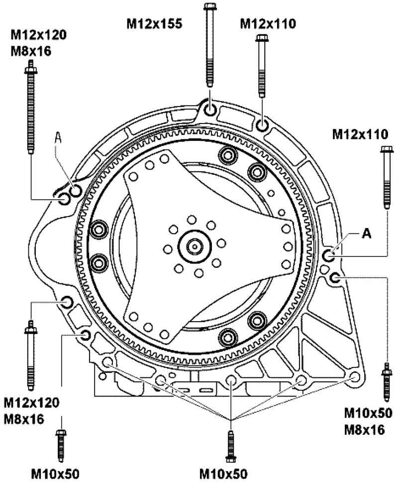
Tightening torques
| Fig. 3.49. Tightening torques of bolts to the engine manual: A - adjusting sleeve
|
See Table. 3.3.
|