add to favorites contacts sitemap
REPAIR MAINTENANCE OPERATION OF MOTOR VEHICLES
Volkswagen Touareg (from 2003 to 2006, the year of issue)

general info. full specifications. diagnostics. hints. tips. tricks
Volkswagen Touareg
Home
 
Volkswagen
Touareg
Operation and maintenance of car
Engine
Transmission
-speed automatic transmission 09D
Check the torque converter
Draining fluid from the torque converter
Install the torque converter
Repair of the drive gear
Removing and installing selector lever
Check and adjust thrust selector
Removing and installing selector rods
Removal and installation of overlays
Removal and installation frame
Removing and installing selector lever lock solenoid N110
Removing and installing selector switch (the lever is locked in position ?�P?�) F319
Removal and installation of the drive gear
Removing and installing the gearbox, cars with diesel engine R5
Removing and installing the gearbox, cars with petrol engines V6 and V8, turbodiesels V6 TDI, V10 TDI and W12 engine petrol
Tightening torques
Removal and installation of lines and ATF cooler
Removing and installing control unit of an automatic transmission J217
Replacement of a sealing ring of a secondary shaft
Removing and installing oil pan
Removing and installing oil strainer
Removal and installation of the hydraulic pressure sensor for the automatic transmission 1 and G193 for hydraulic pressure sensor 2 G194 AKP
Removal and installation of the slide valve box
Removal, installation and adjustment of the multi-function switch F125
Manual transmission and transfer case 08D E473
The propeller shaft
Drive Train
Tables
Chassis
Steering Gear
Brakes
Onboard electric
Body
diagrams


Hit Counter by Digits


print page printable version

Removal, installation and adjustment of the multi-function switch F125


The components of the multifunction switch
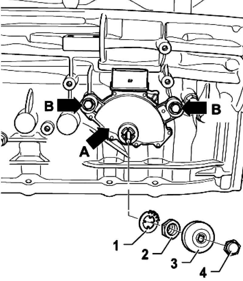
Fig. 3.80. The components of the multifunction switch


Withdrawal
Toggle position ?�P?�.

NOTE
For greater clarity, this process is shown in a previous transmission.

Unscrew the cap nut 4.
3 Remove the cover from selector shaft.
Carefully pry back hooks 1 lock washer with a screwdriver.
If a hook is broken - it is necessary to replace the washer.
After that, remove the nut and lock washer 2 1 from selector shaft.
Disconnect the plug from the multi-function switch F125.
Remove the screws B and remove the multi-function switch to the selector shaft.

Installation and adjustment
Set the lever / selector shaft on the gearbox in position ?�N?�.
Connect the multifunction switch F125 to the selector shaft.
Tighten mounting bolts Vmnogofunktsionalnogo switch F125 by hand.

Setting of the adjustment device
Fig. 3.81. Setting of the adjustment device


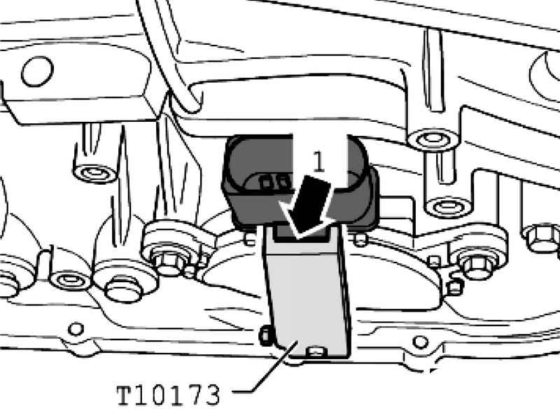
Set the adjusting device T10173 on selector shaft (Fig. 3.81).
Disconnect draft of the selector.
Turn the multifunction switch A so that the tip of the plug 1 was fixed in the groove of the adjusting device T10173.
Tighten the screws to the multi-function switch F125 to 6 N ?� m.
Now remove the adjusting device T10173 from selector shaft.
Connect draft of the selector.
Further installation in reverse order.
Check the adjustment of the thrust selector


« previos page
Removal and installation of the slide valve box
next page »
Manual transmission and transfer case 08D E473

Copyright © 2010 AutoManuals.biz. Trademarks belong to their respective owners. All rights reserved.