printable version printable version
Repair of the drive gear
ATTENTION Before starting work with the engine running, set the selector lever to position ?«P?» and activate the parking brake pedal. |
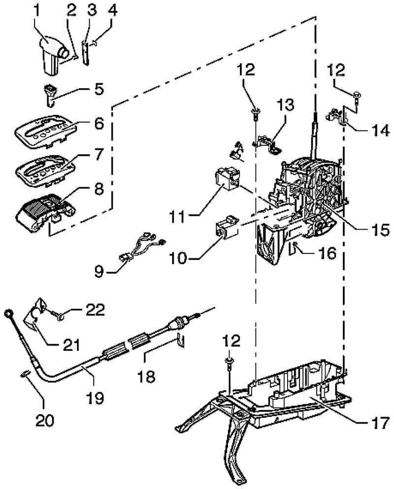
| Fig. 3.7. The components of the drive gear: 1 - the handle of the selector lever; 2 - bracket; 3 - decorative element; 4 - the emblem; 5 - plug; 6 - pad; 7 - guide plate; 8 - frame; 9 - cable; 10 - solenoid lock selector; 11 - lock solenoid selector position P; 12 - a bolt, 20 Nm; 13 - the holder; 14 - the holder; 15 - the drive gear; 16 - a bolt; 17 - a cover; 18 - lock washer; 19 - draft of the selector; 20 - lock washer; 21 - Bearing; 22 - bolt 23 Nm
|
Check the drive gear The selector position ?«R?», ?«D?» and ?«S?» is prohibited to include a starter. In cars with right-hand steering allowed to include starter selector position ?«P?» and ?«N?» only when not pressed the button in the handle of the selector. When the selector is moved to ?«N?» at a speed exceeding 5 km / h, the solenoid locks the selector shall not operate and block selector. The selector must be free to switch to the drive position. When the selector switch in position ?«N?» at a speed less than 5 km / h (the car practically at a standstill), the electromagnetic lock selector shall operate only after about 1 second. From position ?«N?» selector can be switched only when the brake pedal is depressed.
Selector in position ?«P?», the ignition is on Without depressing the brake lever is stuck and can not be switched with the button pressed from position ?«P?». The selector is blocked by an electromagnet. When you press the brake pedal electromagnet unlocks selector. The selector can be switched to the driving position. Slowly the selector switch from position ?«P?» to position ?«S?»; At the same time, check that the position indicator of the selector in the instrument cluster with the real state of the selector.
Selector in position ?«N?», the ignition is on Without depressing the brake lever is stuck and can not be switched with the button pressed from the position ?«N?». The selector is blocked by an electromagnet. When you press the brake pedal electromagnet unlocks selector. The selector can be switched to the driving position.
Celektor in position ?«Tiptronic?» The selector is set to work in the mode Tiptronic. The symbol ?«D?» on the wall switch should turn off the drive should light up the symbols "+" and "-". Display selector position in the instrument cluster when the Tiptronic mode should be changed to ?«PRNDS?» to ?«6 5 4 3 2 1".
Ignition and lighting included Lights corresponding symbol on the wall the drive gear.
The position indicator of the selector The simultaneous illumination of all segments of the selector lever position indicator indicates a fault in the transmission. Check and adjust the thrust selector
|