add to favorites contacts sitemap
REPAIR MAINTENANCE OPERATION OF MOTOR VEHICLES
Volkswagen Touareg (from 2003 to 2006, the year of issue)

general info. full specifications. diagnostics. hints. tips. tricks
Volkswagen Touareg
Home
 
Volkswagen
Touareg
Operation and maintenance of car
Engine
Transmission
-speed automatic transmission 09D
Check the torque converter
Draining fluid from the torque converter
Install the torque converter
Repair of the drive gear
Removing and installing selector lever
Check and adjust thrust selector
Removing and installing selector rods
Removal and installation of overlays
Removal and installation frame
Removing and installing selector lever lock solenoid N110
Removing and installing selector switch (the lever is locked in position ?�P?�) F319
Removal and installation of the drive gear
Removing and installing the gearbox, cars with diesel engine R5
Removing and installing the gearbox, cars with petrol engines V6 and V8, turbodiesels V6 TDI, V10 TDI and W12 engine petrol
Tightening torques
Removal and installation of lines and ATF cooler
Removing and installing control unit of an automatic transmission J217
Replacement of a sealing ring of a secondary shaft
Removing and installing oil pan
Removing and installing oil strainer
Removal and installation of the hydraulic pressure sensor for the automatic transmission 1 and G193 for hydraulic pressure sensor 2 G194 AKP
Removal and installation of the slide valve box
Removal, installation and adjustment of the multi-function switch F125
Manual transmission and transfer case 08D E473
The propeller shaft
Drive Train
Tables
Chassis
Steering Gear
Brakes
Onboard electric
Body
diagrams


Hit Counter by Digits


print page printable version

Removal and installation of the slide valve box


Spool box and / or tubes can be removed / installed as specified in the gearbox, and when removed.

Withdrawal
If the operation is not yet complete - remove the oil pan and the oil strainer

Connectors Sensors
Fig. 3.73. Connectors Sensors


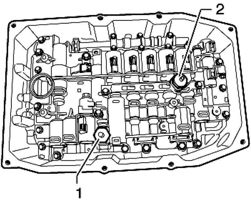
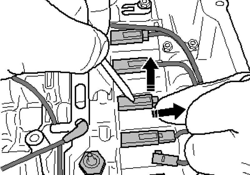
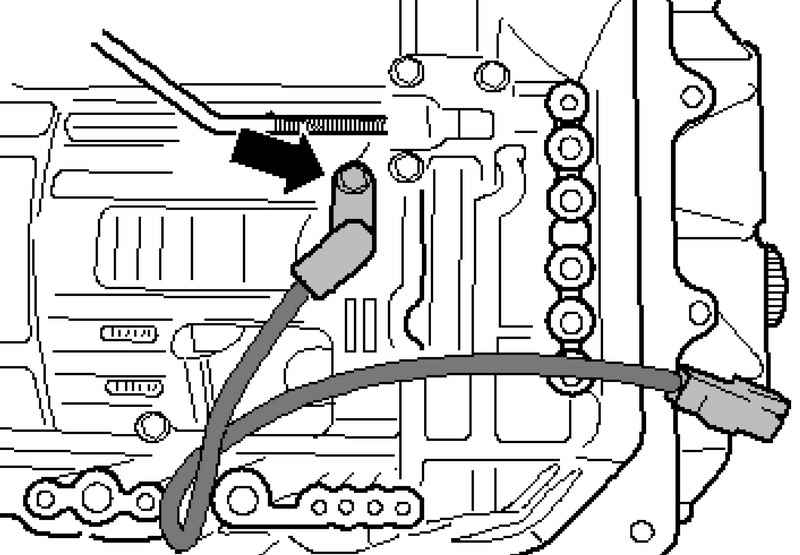
Carefully remove the plugs for the hydraulic pressure sensor 1 in the ACP G1931 and hydraulic pressure sensor for the automatic transmission 2 G1942 (Fig. 3.73).

Plug
Fig. 3.75. Plug


Unscrew the plugs (Fig. 3.75).

Unlock and disconnect plug
Fig. 3.76. Unlock and disconnect plug


Carefully unlock and disconnect plugs (Fig. 3.76).

The oil temperature sensor Gearbox
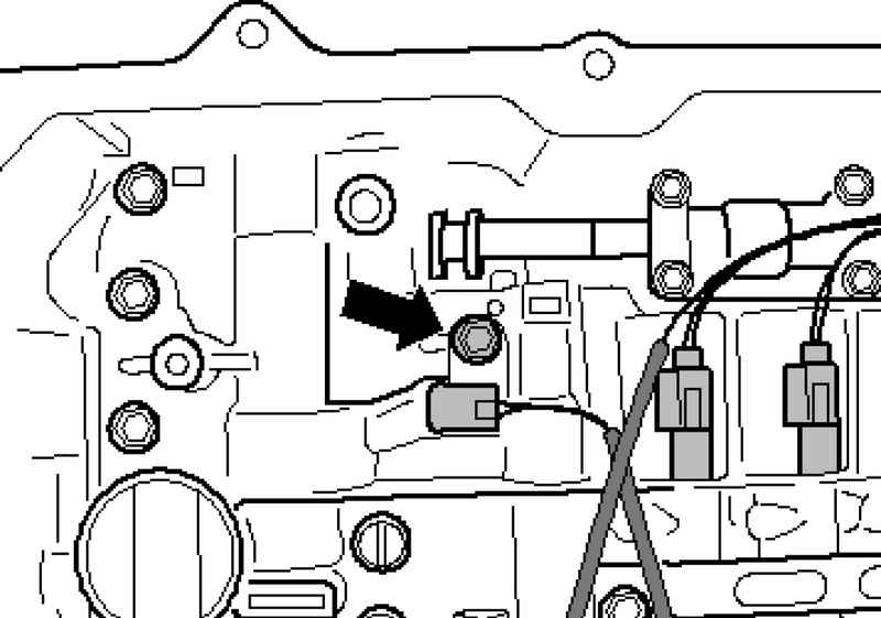
Fig. 3.77. The oil temperature sensor Gearbox


Oil temperature sensor Gearbox G93 tightened to a torque of 10 Nm (Fig. 3.77).

Bolts slide valve box
Fig. 3.78. Bolts slide valve box


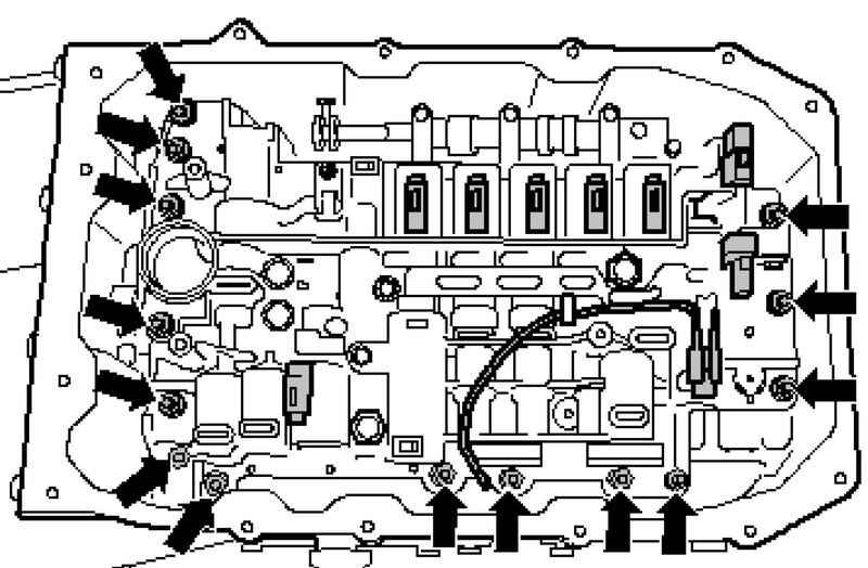
Unscrew the bolts slide valve boxes "criss-cross" (Fig. 3.78).
Torque: 8 Nm + 90 ?�.

The sensor output speed
Fig. 3.79. The sensor output speed


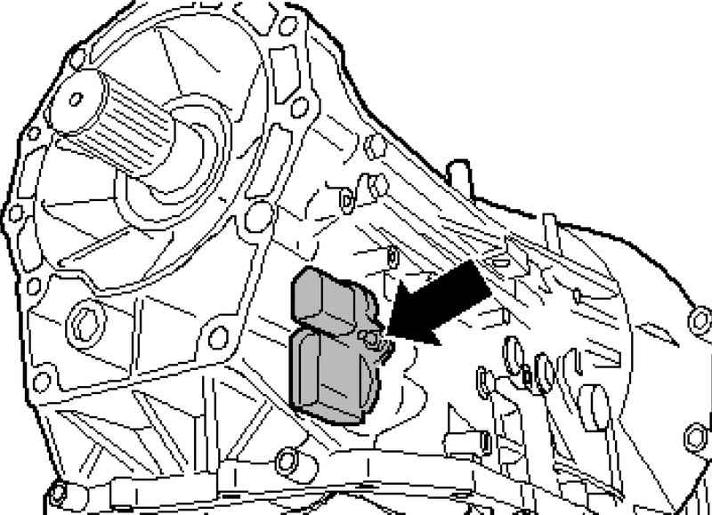
The sensor output speed gearbox G195 is tightened to a torque of 10 Nm (Fig. 3.79).
Installation is carried out in reverse order.
After installation fill the ATF, and then check the level of ATF, if necessary - add oil


« previos page
Removal and installation of the hydraulic pressure sensor for the automatic transmission 1 and G193 for hydraulic pressure sensor 2 G194 AKP
next page »
Removal, installation and adjustment of the multi-function switch F125

Copyright © 2010 AutoManuals.biz. Trademarks belong to their respective owners. All rights reserved.