add to favorites contacts sitemap
REPAIR MAINTENANCE OPERATION OF MOTOR VEHICLES
Volkswagen Touareg (from 2003 to 2006, the year of issue)

general info. full specifications. diagnostics. hints. tips. tricks
Volkswagen Touareg
Home
 
Volkswagen
Touareg
Operation and maintenance of car
Engine
Transmission
-speed automatic transmission 09D
Check the torque converter
Draining fluid from the torque converter
Install the torque converter
Repair of the drive gear
Removing and installing selector lever
Check and adjust thrust selector
Removing and installing selector rods
Removal and installation of overlays
Removal and installation frame
Removing and installing selector lever lock solenoid N110
Removing and installing selector switch (the lever is locked in position ?�P?�) F319
Removal and installation of the drive gear
Removing and installing the gearbox, cars with diesel engine R5
Removing and installing the gearbox, cars with petrol engines V6 and V8, turbodiesels V6 TDI, V10 TDI and W12 engine petrol
Tightening torques
Removal and installation of lines and ATF cooler
Removing and installing control unit of an automatic transmission J217
Replacement of a sealing ring of a secondary shaft
Removing and installing oil pan
Removing and installing oil strainer
Removal and installation of the hydraulic pressure sensor for the automatic transmission 1 and G193 for hydraulic pressure sensor 2 G194 AKP
Removal and installation of the slide valve box
Removal, installation and adjustment of the multi-function switch F125
Manual transmission and transfer case 08D E473
The propeller shaft
Drive Train
Tables
Chassis
Steering Gear
Brakes
Onboard electric
Body
diagrams


Hit Counter by Digits


print page printable version

Removing and installing selector switch (the lever is locked in position ?�P?�) F319


NOTE
Switch Tiptronic-F189 - is built into the harness two electromagnets.

Withdrawal
Remove the selector lever.
You should always observe the sequence off of the battery.
Turn off the mass terminal of the battery when the ignition is off.
Remove the cover of the central console.

Bolts center console
Fig. 3.22. Bolts center console


Remove the center console bolts (Fig. 3.22).
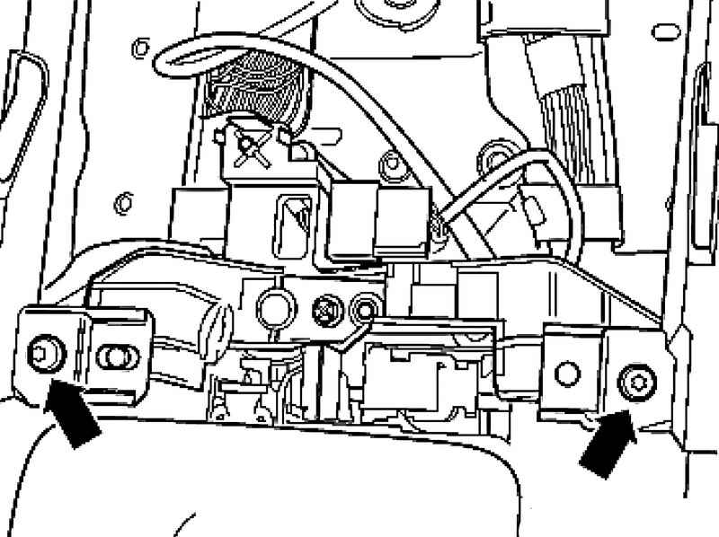
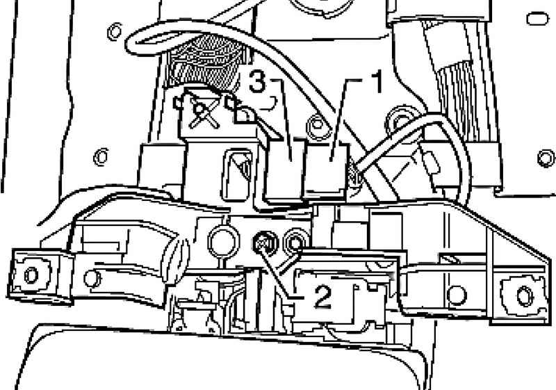
Unlock and disconnect the connector 1.
2 Remove the bolt and remove the holder.

Connectors and bolt
Fig. 3.23. Connectors and bolt


Remove connector 3 from the holder (Fig. 3.23).
Disconnect the connectors from the electromagnets.

The locking lever
Fig. 3.24. The locking lever


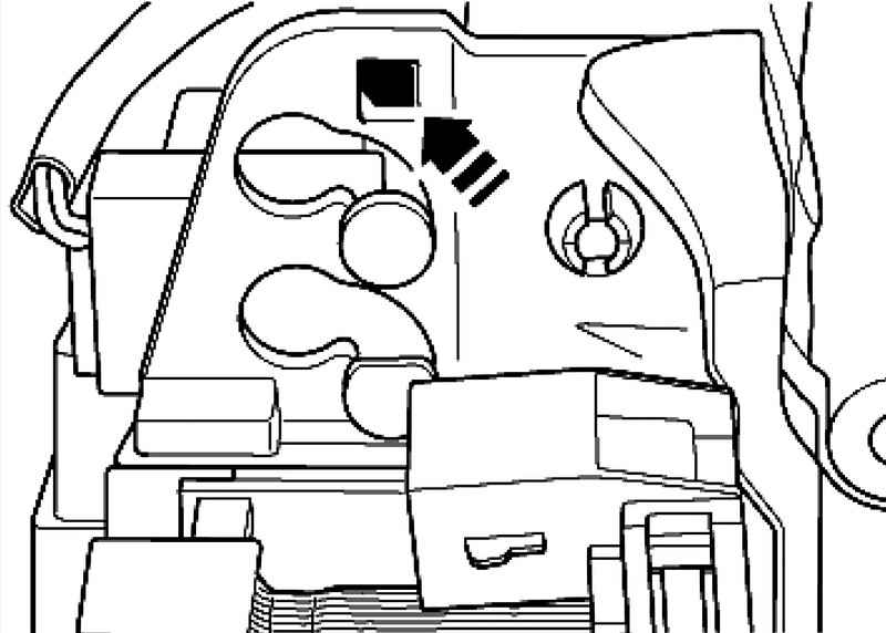
Press the locking lever to the right and pull the switch up and down of the drive gear (Fig. 3.24).

Setting
Installation is carried out in reverse order. It is necessary to consider the following.

Cables
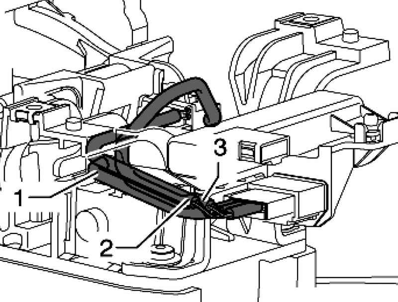
Fig. 3.25. Cables: 1 - the wiring harness to the electromagnet block selector N110; 2 - the wiring harness to the electromagnet lock lever in position ?�P?� N380; 3 - the wiring harness to the selector switch (the lever is locked in position ?�P?�) F319


Lay 1-3 cables as shown (Fig. 3.25).
Install connector 3 in the holder.
Tighten the bolt 2.
Connect the plug 1 (Fig. 3.23).
Install the trim center console.
Connect the battery.
Set the selector lever.


« previos page
Removing and installing selector lever lock solenoid N110
next page »
Removal and installation of the drive gear

Copyright © 2010 AutoManuals.biz. Trademarks belong to their respective owners. All rights reserved.