add to favorites contacts sitemap
REPAIR MAINTENANCE OPERATION OF MOTOR VEHICLES
Volkswagen Touareg (from 2003 to 2006, the year of issue)

general info. full specifications. diagnostics. hints. tips. tricks
Volkswagen Touareg
Home
 
Volkswagen
Touareg
Operation and maintenance of car
Engine
Preliminary checks on the car
The mechanical part (petrol engines 3,2L)
Removal of the power unit
Removal and installation of the left and right engine support cushions
Removing and installing drive plate
Removing and installing oil seal on the flywheel side
Replacing the oil seal on the side of the crankshaft vibration damper
Replacement of sealing flange on the side of the crankshaft vibration damper
Removing and installing crankshaft
Removing and installing the side cover
Removing and installing cylinder head cover
Removal and installation of the cylinder head
Checking the valve timing
The timing
Removing camshafts
Installing the camshaft
Checking the axial displacement of the camshaft
Marking camshafts
Replacing valve stem seals
Checking the valve guides
Processing valve seat
Valve sizes
Checking the pistons, piston rings and cylinder bore
The mechanical part (petrol engines 4,2L)
The mechanical part (diesel engines 5,0L)
Removing and installing subframe
Pressurization system (diesel engines)
Cooling system (petrol engines)
The cooling system (diesel engines)
Lubrication (petrol engines)
Lubrication system (diesel engines)
Injection System (petrol engines)
Fuel injection system (diesel engines)
Exhaust
FUEL (beninovye engines)
Tables
Transmission
Chassis
Steering Gear
Brakes
Onboard electric
Body
diagrams


Hit Counter by Digits


print page printable version

Checking the valve timing


NOTE
Valve timing can be checked with the engine installed.

Checking procedure
Remove the intake manifold and cylinder head cover.
Remove front noise insulation.

Installation 1 cyl. TDC
Fig. 2.58. Installation 1 cyl. TDC


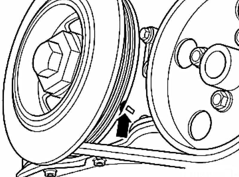
Turn the crankshaft with the mounting bolt vibration damper in direction of rotation of the engine to the level of TDC cyl. 1 (Fig. 2.58).
Ruler camshaft T10068 A should be included in both grooves.
If you put a line for the camshafts can not again turn the crankshaft in the direction of rotation of the motor.

NOTE
If the ruler camshaft T10068 A still included, turn the crankshaft in the direction of rotation of the motor by about 5 mm above the TDC cyl. 1 (depending on the timing chain tolerances).

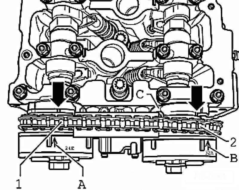
Compare adjusting phase shifters mark stamped on the timing cover.

Combining marks on the phase shifters scored timing cover
Fig. 2.69. Combining marks on the phase shifters scored timing cover


Marks A and B to coincide with the phase shifters have notched timing cover C (Fig. 2.69).
The distance between the tooth and the tooth 1 2 stars phase shifters should be exactly 16 chain rollers.

NOTE
Figure 2.69 shows a system variable valve timing when the cover is removed.

If the marks do not coincide, adjust the timing.
If the same mark set cylinder head cover and intake manifold.


« previos page
Removal and installation of the cylinder head
next page »
The timing

Copyright © 2010 AutoManuals.biz. Trademarks belong to their respective owners. All rights reserved.