printable version printable version
The timing
NOTE Install the timing chain. These mounting operations can be performed only on the removed engine |
The order of execution of works
ATTENTION In any assembly work, particularly in the engine compartment due to the tight layout, consider the following: - All line types (such as fuel, hydraulic absorber, activated carbon, cooling systems, circuit conditioning systems, brake lines, vacuum tubes), and also necessary to lay electric wires as they were originally laid. Provide space for all moving or hot components. |
NOTE Camshaft drive chain can be removed only when the engine is removed. The following operations begin when the engine exploded. Thus, it is possible to start from a point adjustment depending on how the engine disassembled. |
Install roller chain and chain tensioner intermediate shaft tensioning strap.
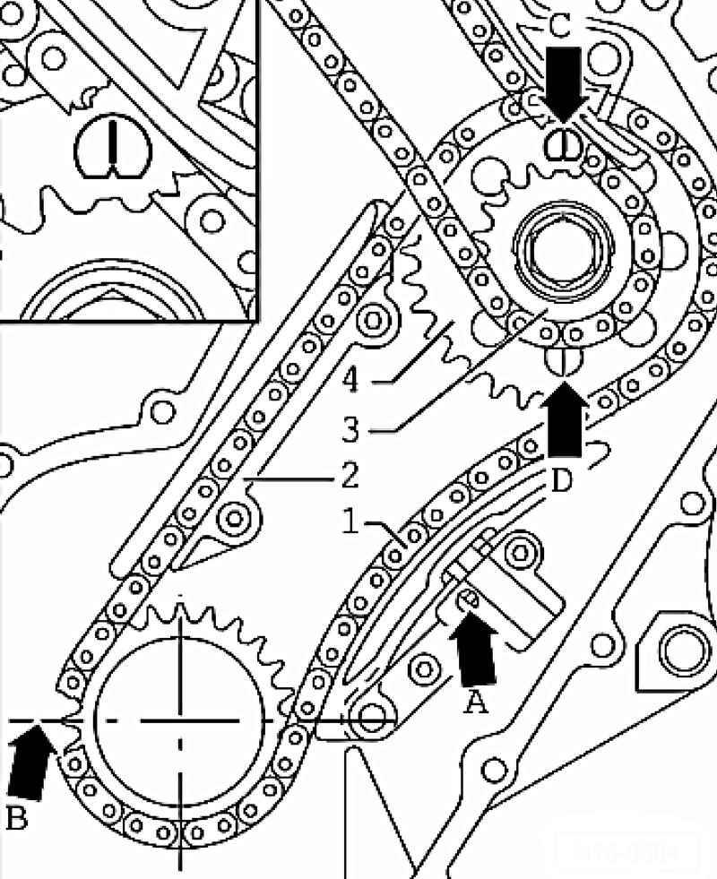
| Fig. 2.70. Combining tooth sprocket with a joint bearing "TDC cylinder 1"
|
Adjust the position of the crankshaft relative to the intermediate shaft. For this polished tooth drive sprocket B should coincide with a joint bearing "TDC cylinder 1" (Fig. 2.70). Install two bolts without collar for mounting the guide bar 2 and tighten them to 10 Nm.
NOTE If roller chain has been used previously, it is necessary to take into account the specified direction of rotation. |
Install guide bar 2 with 1 roller chain and two chain sprockets 3 and 4. Marking on roller chain sprocket 4 must be in alignment with the notch C or D on the shim intermediate shaft (Fig. 2.70). Installation must see to it that the roller is moved inside the guide bar from the crankshaft to the intermediate shaft, without any sagging. Manually screw the sprocket 3 and 4 to the intermediate shaft.
NOTE Pay attention to the need to replace all the bolts Stars. |
Set on the opposite side of the chain tensioner. Unlock locking gearing chain tensioner A with a small screwdriver and press tensioning bar chain tensioner. In this position, set the chain tensioner and tighten it to 8 Nm. Secure vibration damper with a key to lock the T10069. Tighten the new fixing bolt stars 3 and 4 for the chain drive intermediate shaft with a torque of 60 Nm + 1/4 about. (90 ?°). Remove the counter support T10069. Recheck the crankshaft position B with respect to the intermediate shaft C or D (Fig. 2.70). Once again, bring the engine to TDC cyl. 1. Install roller timing chain. Give installed camshafts in cylinder head to TDC cyl. 1.
NOTE If necessary, turn camshafts with a wrench 32 in the correct position. Ruler camshaft T10068 A should not be at the same time embedded in the groove. |
|