printable version printable version
Installing the camshaft
NOTE When installing the camshaft cams for the first cylinder should look up. |
The order of execution of works
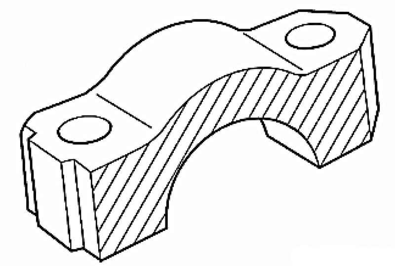
| Fig. 2.75. The adjacent surface of the bearing cap
|
Before installation grease contact surfaces of bearing caps 7 and 8, a small amount of grease G 052 723 A2 (Fig. 2.75). Insert the supporting elements in cylinder head and check the corresponding roller levers to the ends of cores of valves and their support.
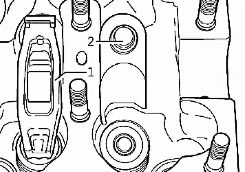
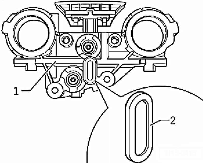
Ensure that all roller lever 1 correctly attached to the ends of the valve stems and zaklipsovany the respective support element 2 (Fig. 2.76). Grease a working surface of cam engine oil. Gently insert the corresponding camshaft bearings camshaft cylinder head. At the same time marked Check camshafts.
NOTE Observe the installation position of the bearing cap. |
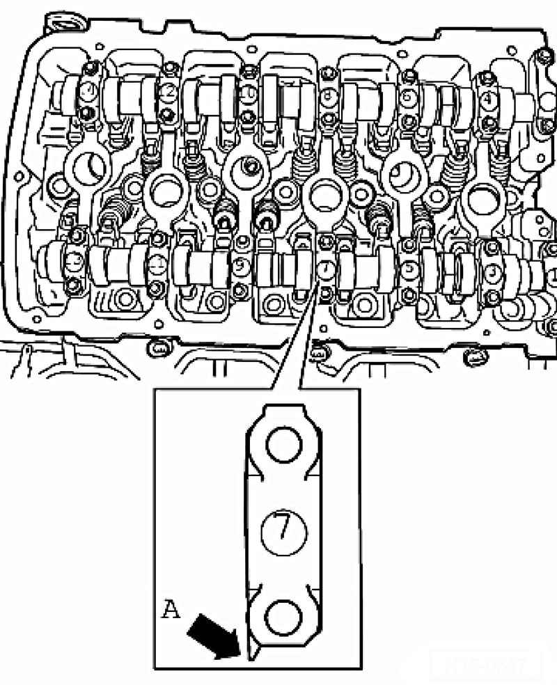
Myski bearing caps A intake and exhaust camshafts point out.
Marking the bearing cap is visible from the side of the intake camshaft (Fig. 2.77).
Inlet camshaft Screw the bearing caps 5 and 9 alternately crosswise and tighten with a torque of 5 Nm + tighten 1/8 turn. (45 ?°). Install bearing caps 1 and 13 and tighten with a torque of 5 Nm and 1/8 turn (45 ?°). Install bearing cap 7 and tighten with a torque of 5 Nm and 1/8 turn (45 ?°). Install bearing caps 3 and 11 and also tighten with a torque of 5 Nm and 1/8 turn (45 ?°).
The exhaust camshaft Screw the bearing caps 6 and 10, alternating crosswise and tighten with a torque of 5 Nm + tighten 1/8 turn. (45 ?°). Install bearing caps 2 and 14 and tighten with a torque of 5 Nm and 1/8 turn (45 ?°). Install bearing cap 8 and tighten with a torque of 5 Nm and 1/8 turn (45 ?°). Install bearing caps 4 and 12 and also tighten with a torque of 5 Nm and 1/8 turn (45 ?°).
Continuation for both camshafts Give camshafts in cylinder head to TDC cyl. 1. Ruler camshaft T10068 A should be included in both grooves. Before installation, check the strainer cover distribution mechanism for contamination. Before installing the timing cover lightly grease with engine oil seals adjacent surfaces of camshafts in the timing cover. Lightly oil the surface of the adjacent lip seals on the camshafts and slowly slide the timing cover to the camshaft oil seals. Install the timing cover (Fig. 2.77) and tighten the bolts to 8 Nm.
The timing Clean 3-mm holes in the cylinder head gasket from the remnants of the old sealant.
NOTE With the cylinder head installed the holes in the cylinder head gasket are only visible half. |
Fill 3 mm holes in cylinder head gasket with sealant AMV 174 004 01 and at these points apply sealant little more.
NOTE Sealant AMV 174 004 01 hardens quickly. |
Lubricate the O-ring of the oil channel with engine oil and insert it into the side cover with the omentum. Lubricate the seat surface on the side of the lid sealant AMV 176 501 and immediately insert it. First insert all securing bolts and tighten them slightly. Then tighten the M8 bolts to 23 Nm then M6 bolts with torque 8 Nm. Install chain tensioner timing and tighten the bolts with a torque of 40 Nm. Install the cylinder head cover and intake manifold.
Dismantling and assembling timing cover Check the mesh filter in the cover of the distributive mechanism for contamination.
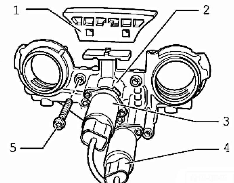
| Fig. 2.78. Timing cover: 1 - Strap pacifier: zaklipsovana on timing cover; 2 - a cover of the distributive mechanism; 3 - 1 valve variable valve timing system; 4 - the valve of 1 system of variable valve timing of exhaust valves; 5 - a bolt
|
Rasklipsuyte screen 2 on the back of timing cover 1 and remove any dirt (Fig. 2.79).
|