printable version printable version
Removing camshafts
NOTE Removing and installing the camshaft is possible only at the removed engine and cylinder head. |
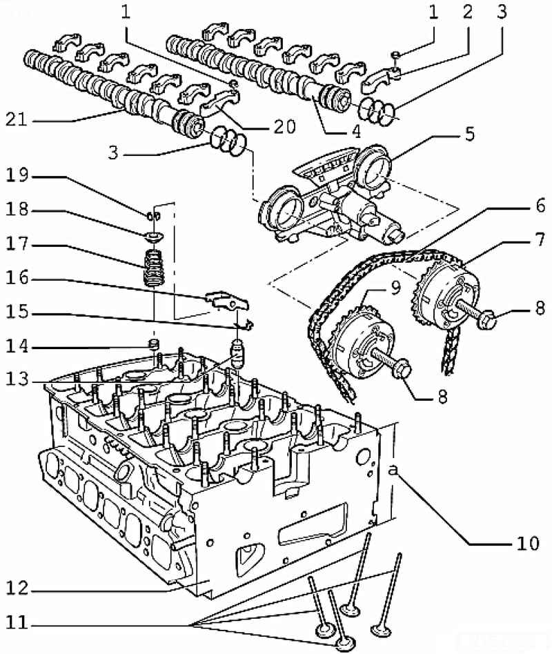
| Fig. 2.71. The components of the distribution mechanism: 1 - a bolt; 2 - a cover of the bearing of a final camshaft; 3 - O-ring; 4 - the exhaust camshaft; 5 - timing cover; 6 - roller chain drive camshafts; 7 - the exhaust camshaft phase shifter; 8 - a bolt; 9 - phaser intake camshaft; 10 - the height of the cylinder head; 11 - valve; 12 - cylinder head; 13 - support member; 14 - the valve stem seal; 15 - lock bracket; 16 - roller lever; 17 - a spring valve; 18 - the valve spring plate; 19 - cracker valve; 20 - a cover of the bearing of the intake camshaft; 21 - the inlet camshaft
|
The order of execution of works Priveditekolenval with mounting bolts vibration damper in direction of rotation of the engine to the level of TDC cyl. 1. Remove the intake manifold and cylinder head cover. Remove the thermostat housing. Remove the timing chain tensioner. Unscrew the camshaft.
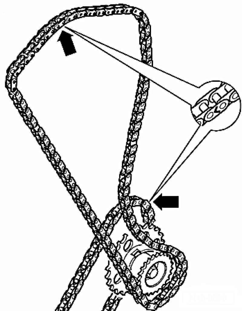
Before removing, mark direction of rotation of roller chains (eg. Apply paint an arrow indicating the direction of the chain) (Fig. 2.72).
NOTE Do not apply a notch punch or similar tool. |
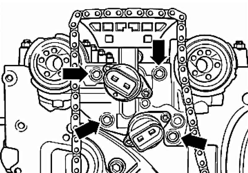
First remove the coupling permutations of the exhaust camshaft. Hold the cam in a fixed position should only be using the spanner 32. When tightening or loosening phase shifters line camshaft T10068 A should not be embedded in the groove. Remove the coupling permutations camshaft with roller chain timing from the intake shaft. Put the timing chain to the side, putting her side.
Carefully remove timing cover with lip seals camshafts.
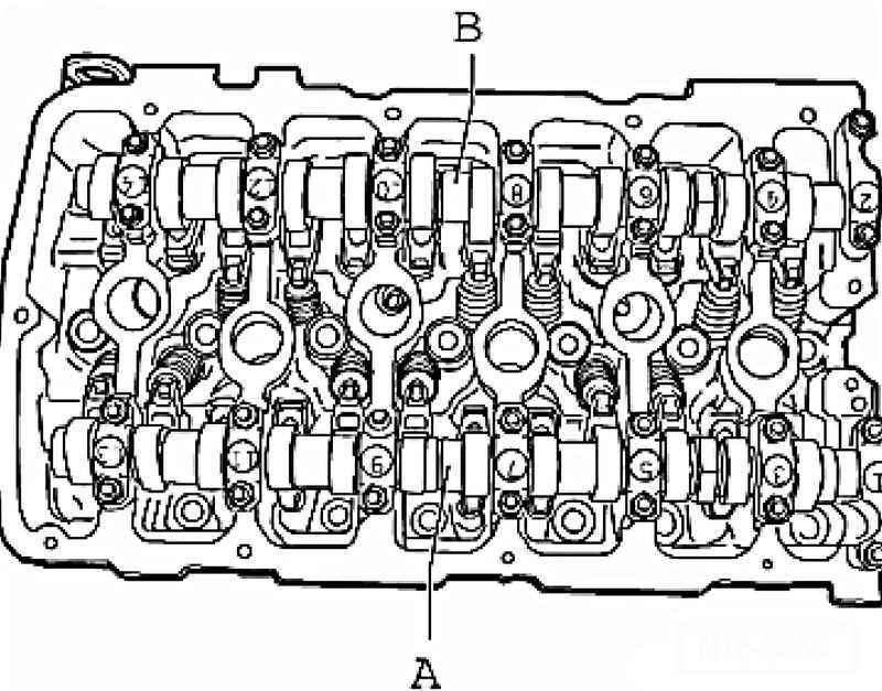
Inlet camshaft Remove the first bearing caps 1 and 13. Then remove the bearing caps 3 and 11. Remove the cover bearing 7.
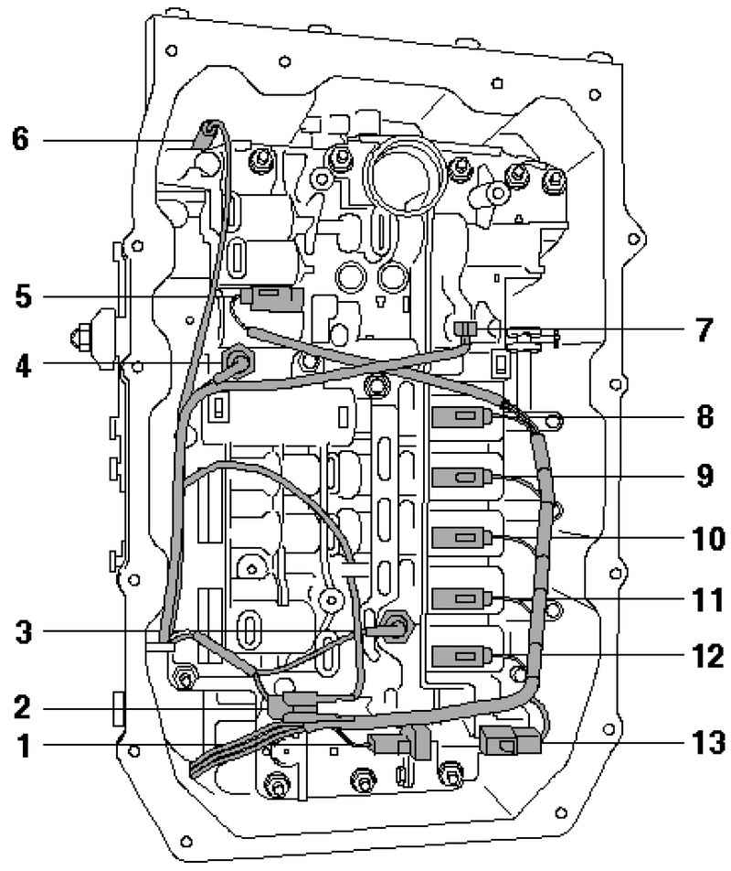
| Fig. 3.74. Components of the slide valve boxes: 1 - 2 solenoid valve; 2 - plug connection of the sensor output speed gearbox; 3 - pressure sensor for hydraulic automatic transmission 2 G194; 4 - the gauge of pressure in the hydraulic system 1 AKP G193; 5 - the electromagnetic valve 4; 6 - the gauge of the output shaft speed manual; 7 - oil temperature gauge gearbox; 8 - solenoid valve 6; 9 - 3 solenoid valve; 10 - solenoid valve 5; 11 - solenoid valve 10; 12 - solenoid valve 1
|
Loosen and remove bearing caps 5 and 9 alternately crosswise (Fig. 3.74).
The exhaust camshaft Remove the first bearing caps 2 and 14. Then remove the bearing caps 4 and 12. Remove bearing cover 8.
Loosen and remove bearing caps 6 and 10, alternating crisscross pattern (Fig. 2.74). Carefully remove camshafts and place them on a clean surface. Remove the roller lever with the legs and put them on a clean surface. It is forbidden to swap the roller lever and the supporting elements.
|