printable version printable version
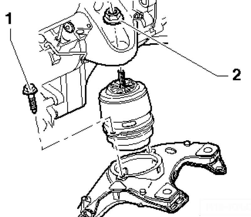
Removal and installation of the left and right engine support cushions
Withdrawal Remove the air filter assembly from the flow sensor. Turn off fixing nuts 2 on the left and right engine mountings.
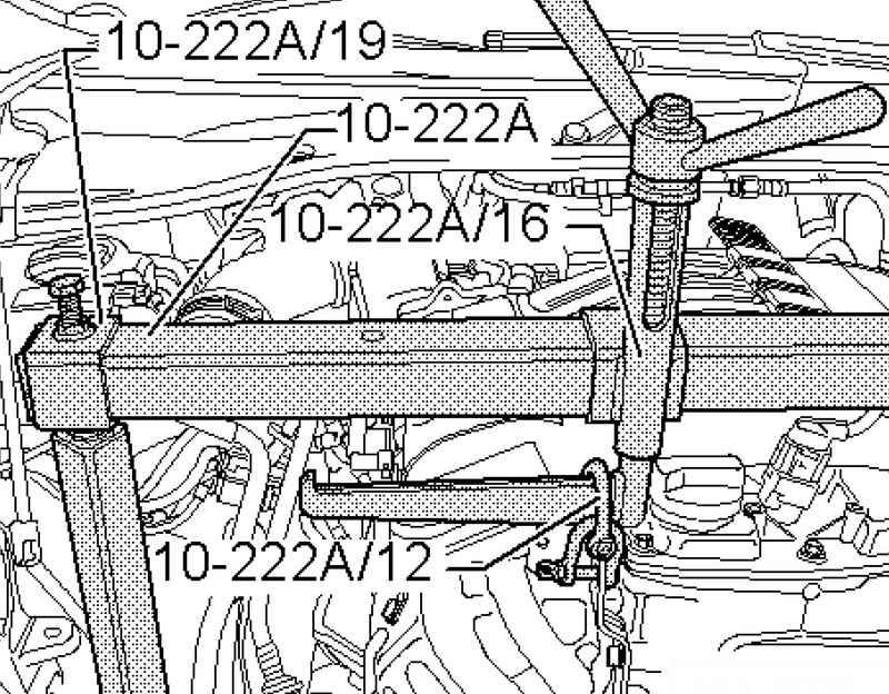
Insert the adapter in Traverse 10-222A 10-222A / 16 high side guide lead screw up, as shown in Figure 2.39. Then insert the adapter 10-222A / 19 in Traverse 10-222A right and left. Install yoke 10-222A on spars.
Pick up the engine two earrings 10-222A / 12 to the adapter 10-222A / 16 and slightly tighten it (Fig. 2.40). Then, unscrew the fixing bolts 1 of the left and right engine mountings / stretcher. If necessary, use the free space between the cylinder head and the front wall. Now carefully lift the engine using a crane 10-222A / 16. To remove pillows engine mount must also loosen the left or right engine mounts from the cylinder as long as the engine can not be raised high enough.
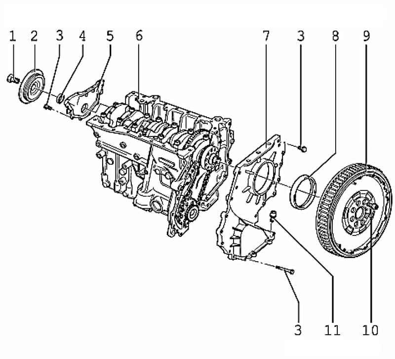
| Fig. 2.41. Arrangement of sealing flanges: 1 - a bolt; 2 - vibration damper; 3 - a bolt; 4 - gland; 5 - sealing flange; 6 - cylinder block; 7 - sealing flange; 8 - gland; 9 - two-mass flywheel; 10 - a bolt; 11 - a bolt
|
Setting Installation is performed in reverse order. When setting Check the correct fit of the pin cushion engine support. First Loosely all fixing bolts by hand, only then tighten them to the specified torque. The tightening torque of the fastening bolt 1: 60 Nm. The tightening torque of the fastening bolts 2: 75 Nm. Tightening torque of fixing bolts of the oil filter housing / engine support on the left cylinder block 23 Nm. Tightening torque of the fastening bolts on the right support of the engine cylinder block 40 Nm.
|