add to favorites contacts sitemap
REPAIR MAINTENANCE OPERATION OF MOTOR VEHICLES
Volkswagen Touareg (from 2003 to 2006, the year of issue)

general info. full specifications. diagnostics. hints. tips. tricks
Volkswagen Touareg
Home
 
Volkswagen
Touareg
Operation and maintenance of car
Engine
Preliminary checks on the car
The mechanical part (petrol engines 3,2L)
Removal of the power unit
Removal and installation of the left and right engine support cushions
Removing and installing drive plate
Removing and installing oil seal on the flywheel side
Replacing the oil seal on the side of the crankshaft vibration damper
Replacement of sealing flange on the side of the crankshaft vibration damper
Removing and installing crankshaft
Removing and installing the side cover
Removing and installing cylinder head cover
Removal and installation of the cylinder head
Checking the valve timing
The timing
Removing camshafts
Installing the camshaft
Checking the axial displacement of the camshaft
Marking camshafts
Replacing valve stem seals
Checking the valve guides
Processing valve seat
Valve sizes
Checking the pistons, piston rings and cylinder bore
The mechanical part (petrol engines 4,2L)
The mechanical part (diesel engines 5,0L)
Removing and installing subframe
Pressurization system (diesel engines)
Cooling system (petrol engines)
The cooling system (diesel engines)
Lubrication (petrol engines)
Lubrication system (diesel engines)
Injection System (petrol engines)
Fuel injection system (diesel engines)
Exhaust
FUEL (beninovye engines)
Tables
Transmission
Chassis
Steering Gear
Brakes
Onboard electric
Body
diagrams


Hit Counter by Digits


print page printable version

Removing and installing cylinder head cover


Withdrawal
After installation, you must reinstall all fasteners cable, remove or cut during removal.
Remove the engine cover.
Remove ignition coils with output stages.
Remove the hose between air mass meter G70 and the throttle control unit.
Disconnect the 6-pin connector from the control module throttle J338, as well as 2-pin connector of the solenoid valve 1 activated charcoal canister N80 and crankcase ventilation valve.
Disconnect vacuum hoses from an inlet collector 1-3. On cars with the letter designation of the engine BAA and BMX additionally remove the vacuum hose from the intake manifold 4.

Fixing bolt intake manifold support
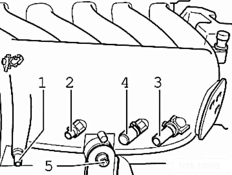
Fig. 2.56. Fixing bolt intake manifold support


Remove the mounting bolt 5 supports the intake manifold (Fig. 2.56).
Then, unscrew the mounting intake manifold right and left at the collector.
Disconnect the hose crankcase ventilation of the cylinder head cover.

Fixing bolts of the intake manifold
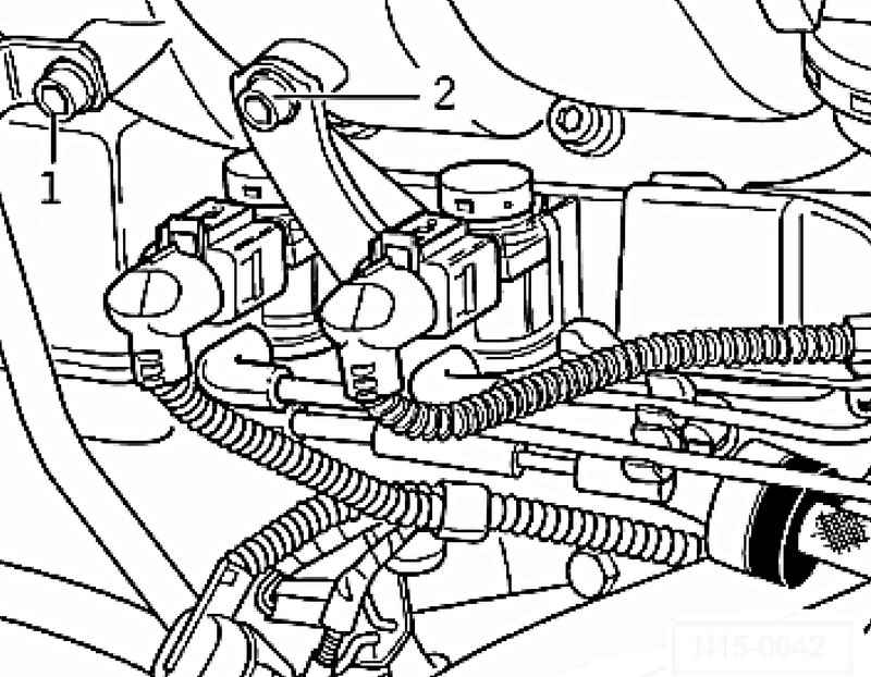
Fig. 2.57. Fixing bolts of the intake manifold


Loosen cap screws 1 and 2 in the intake manifold (Fig. 2.57).
Disconnect the vacuum hose from the vacuum actuator switching intake manifold.
Remove the intake manifold from the cylinder head.
Remove the inlet pipe and place it on a clean surface so as not to damage the vacuum actuator element.

NOTE
The inlet channels in the inlet manifold and the cylinder head should be covered with a clean cloth.

The front of the cylinder head cover unscrew the wire to the knock sensor 1 and sensor G61 level and oil temperature G266.
Remove the cylinder head cover.

Setting
Installation is performed in reverse sequence, with the following features.
The intake manifold must first be bolted to the cylinder head.
Then tighten the two screws and bolts the heat shield backups inlet.
Check the tightness of fastening the fuel hoses.

Tightening torques


« previos page
Removing and installing the side cover
next page »
Removal and installation of the cylinder head

Copyright © 2010 AutoManuals.biz. Trademarks belong to their respective owners. All rights reserved.