printable version printable version
Removal of the power unit
NOTE The engine is removed together with the gearbox down. |
ATTENTION The fuel is pressurized. to avoid injuries and skin contact, wear protective goggles and gloves. Before disconnecting the connection hose wrap cloth. Then release pressure by gently loosening the connection. |
Preliminary Steps To ensure the smooth scrolling of the propeller shaft, set the selector lever in position ?«N?». To prevent the steering lock, leave the key in the ignition. Before dismantling the power unit is recommended to remove the front wheels. In this way, the car can be lowered on the lift, leaving between the casing of the brake discs and the floor a few centimeters. Thus, during operation reach the optimal level of all components in the engine compartment. To avoid damage to the parts removed, use the container for removed parts VAG 1698. Some components in the vehicle can not or difficult to disassemble without removing the engine. Therefore, before removing motor is necessary to determine all defective parts and after removal of the engine to replace them. Turn the ignition and all electrical consumers. Disconnect the battery under the driver's seat.
Removal of the power unit with the gearbox assembly Remove the left and right wiper arms. Remove the bonnet seal to the front wall.
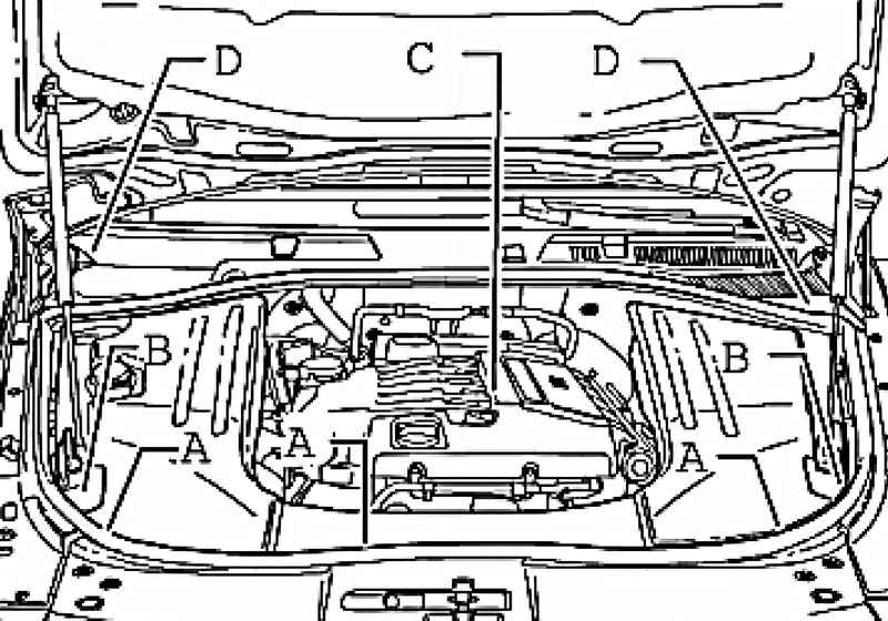
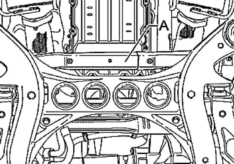
Remove the cover A, B and C in the engine compartment, and D plenum chamber (Fig. 2.19).
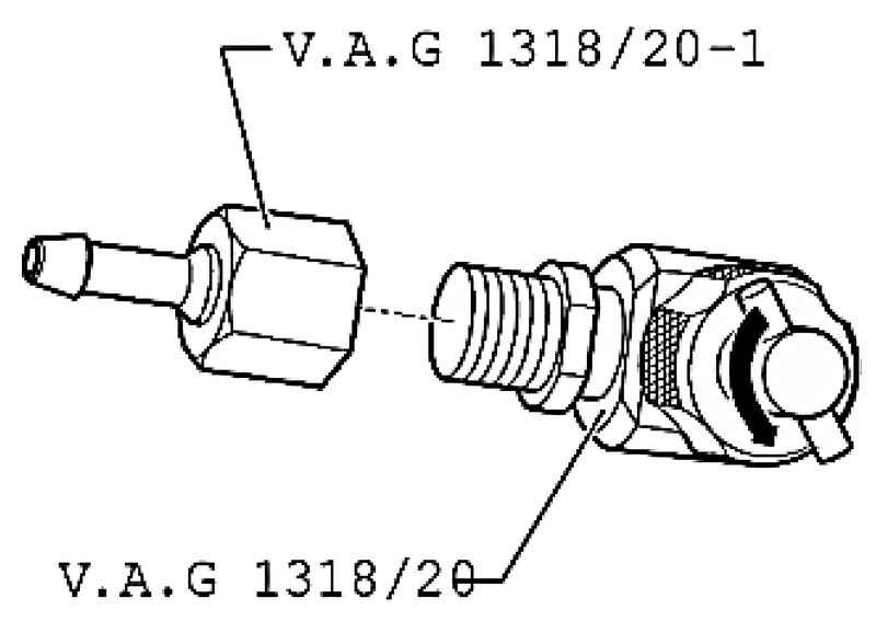
Screw adapter VAG 1318 / 20-1 adapter VAG 1318/20 (Fig. 2.20). Turn valve (on the T-adapter) counter-clockwise and open it completely.
ATTENTION Before depressurization of the fuel system, connect a pumping device VAS 5226 and relieve the pressure. |
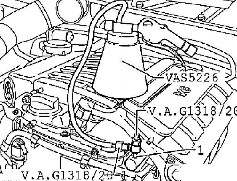
Remove the protective cover of the air valve. Connect the air valve 1 Adapter VAG 1318/20 Adapter VAG 1318 / 20-1 and the evacuating device VAS 5226.
Screw the valve (on the T-adapter) clockwise until it stops in the air valve (Fig. 2.21). After the fuel pressure drop can depressurize the fuel system. Under the joint further enclose rags to soak up leaking fuel.
After the installation of the engine must be in the same places to re-establish all cable clamps, remove or cut for its dismantling.
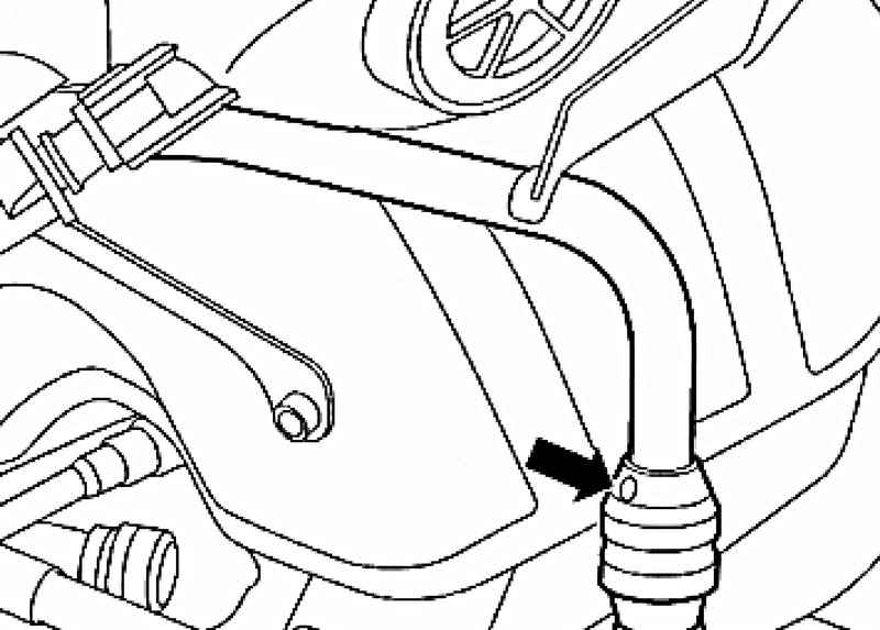
Disconnect the vent line to the solenoid valve 1 absorber N80's engine compartment (Fig. 2.23).
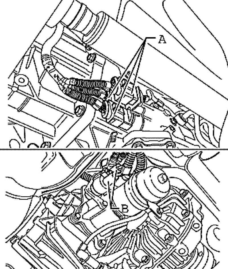
| Fig. 2.24. Disconnect the connector from the engine control unit and disconnect the wire harness weight
|
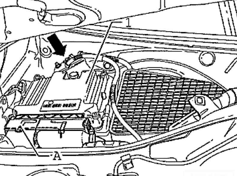
Disconnect the small connector A of engine control unit and unplug the wire harness weight (Fig. 2.24).
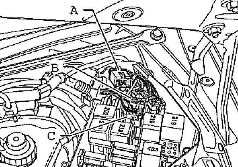
Open the cover of the fuse box, to the left in the plenum chamber and disconnect the connectors A, B and C (Fig. 2.25). Remove the wiring harness from plenum chamber and place it on the engine.
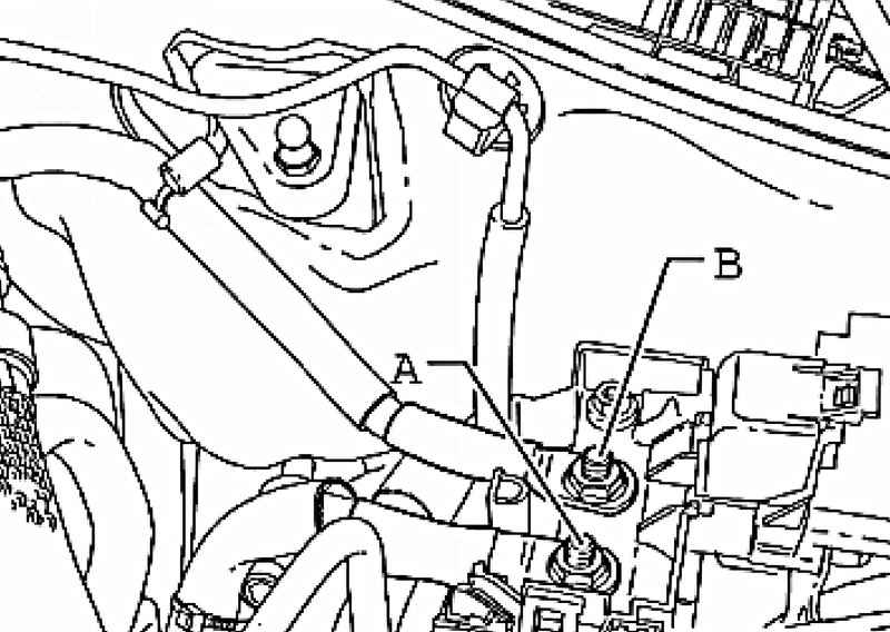
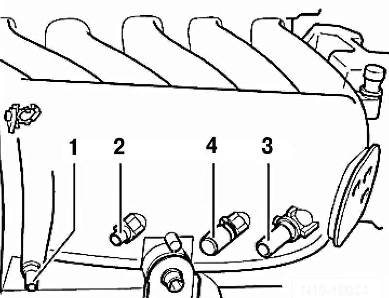
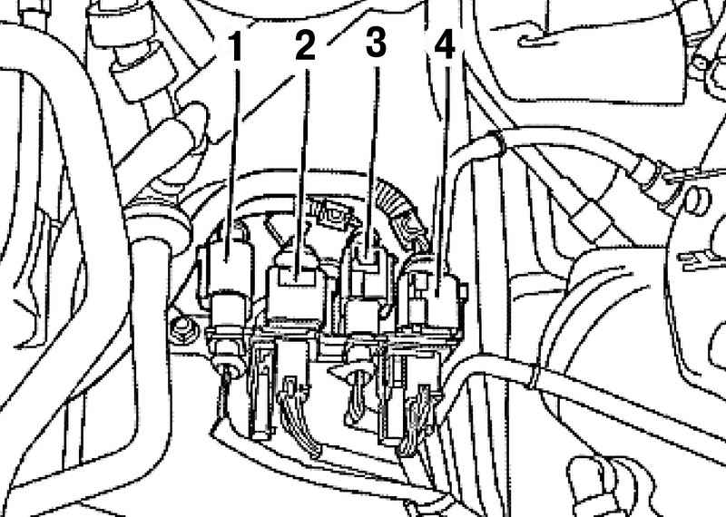
Disconnect the starter generator A and B, and put them on the engine (Fig. 2.26). Disconnect vacuum hoses from an inlet collector 1-3.
On cars with the letter designation of the engine BAA further remove the vacuum hose from the intake manifold 4 (Fig. 2.27).
| Fig. 2.28. Hose connections secondary air pump
|
Disconnect the hose from the secondary air pump (Fig. 2.28).
Disable plugs 1-4 lambda probes and put the plugs on the engine (Fig. 2.29). Cylinders 1-3: black. Cylinders 4-6: brown.
| Fig. 2.30. The connection pipe to the compressor air suspension
|
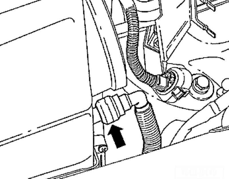
Disconnect the pipe to the compressor air suspension from the air filter (arrow in Figure 2.30) in the manner described below.
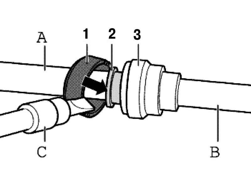
Gently pry the lock ring 1 green screwdriver. Then push down on the clamp ring 2 in the direction of the arrow in Figure 2.31. Then unplug the weakened pipe fitting B of A on the air filter. Remove the top part of the air filter up. Unlock and remove the crankcase ventilation pipe from the gearbox housing of the air filter. Evacuate refrigerant from the air conditioner.
ATTENTION When you open the expansion tank from it can go hot steam. in order to avoid eye injuries and scalding, put on safety goggles and special clothing. Cover bull cloth and gently loosen it. |
Drain the coolant. Disconnect the upper radiator hose and the lower radiator hose from the tube.
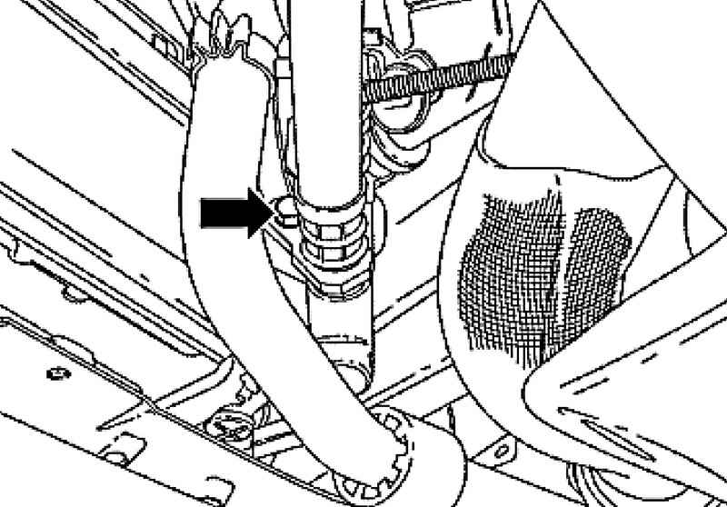
| Fig. 2.32. Fixing transmission oil cooler tube
|
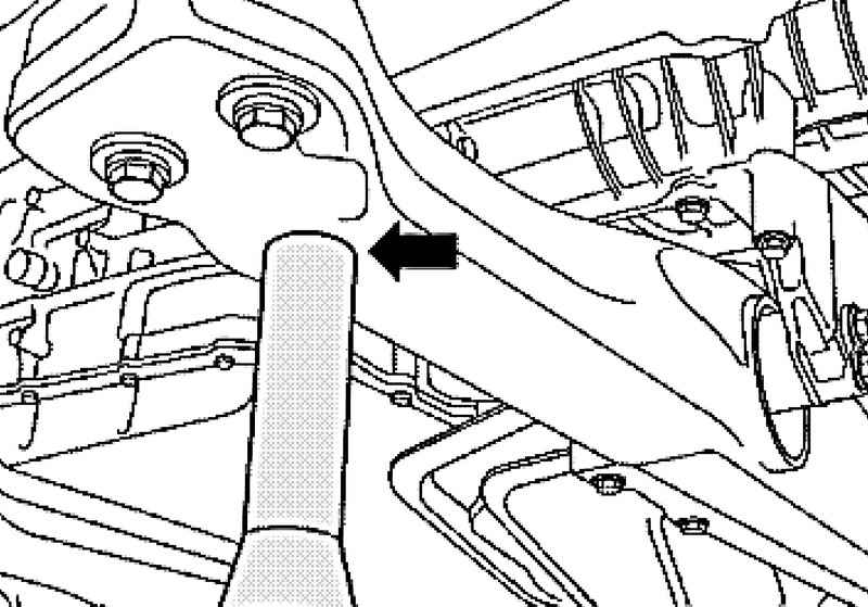
Disconnect the tube (arrow in Figure 2.32) from the cooler transmission oil at the bottom right. Place a receptacle under the escaping oil. Then disconnect the pipe from the hydraulic oil cooler at the lower left. Place a receptacle under the escaping oil. Free double clamp between the catalytic converter and intermediate muffler, and then slide the clamp forward. Lean the silencer on the counter for the engine and gearbox VAG 1383A, unscrew the back of the pendant mounting of the exhaust system and lower it. Remove heat shield on the steering mechanism and loosen the universal joint.
| Fig. 2.33. Connectors transmission and transfer case
|
Disconnect A on the gearbox and transfer box B and unhook the selector rod (Fig. 2.33) Remove the rear driveshaft. Remove the front wheels. Remove the front wheel arches. Disconnect the wheel housing in the brake pipes from the brake hose and collect the flow of fluid. Disconnect all connectors between body and front axle in wheel niches. Remove the pipes from the air suspension strut.
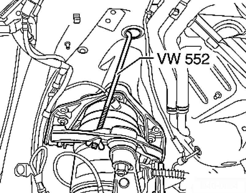
Fix the strut as shown in Figure 2.35 by a spring fixture 552 VW. Unscrew on each side of the car on the upper strut bolts. Set the timeline for further work on the removal of the engine.
| Fig. 2.36. Summing racks timeline for powertrain
|
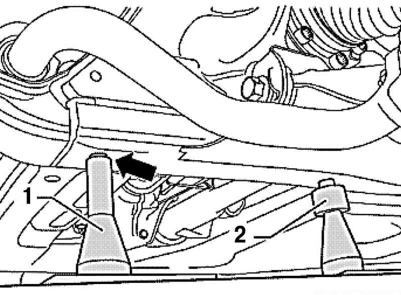
Move horizontally aligned timeline for the power unit. 1 supports must enter the left and right in the corresponding slot (Fig. 2.36).
| Fig. 2.37. Summing up the supports for the gearbox console
|
At the same time, enter the right and left support for the console transmission in a corresponding hole (Fig. 2.37). When all four legs are fixed in foster holes without pressure, unscrew the two plates with a little tension conductors under suspension arms so that you can remove suspended for insurance spring fixture VW 552.
| Fig. 2.38. Installation of supports for the stretcher
|
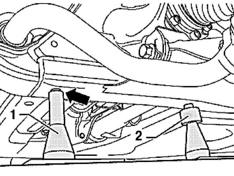
Enter the support 2 into the appropriate slots in a stretcher, if necessary, adjust the height of the supports by means of the knurled nut (Fig. 2.38). Unscrew subframe bolts 1, 2 and 3, as well as cross gearbox 4.
NOTE After removing the sub-frame is necessary to adjust the angles of the wheels. |
Slowly lower down the power unit, continuously monitoring the progress unhindered.
|