printable version printable version
Removal and installation of the cylinder head
Withdrawal
NOTE The operation to remove the cylinder head is carried out on the removed engine. |
The engine should be warm to the touch.
ATTENTION In any assembly work, particularly in the engine compartment due to the tight layout, consider the following: - All line types (such as fuel, hydraulic absorber, activated carbon, cooling systems, circuit conditioning systems, brake lines, vacuum tubes), and also necessary to lay electric wires as they were originally laid. - Provide space for all moving or hot components. - After installation, you must reinstall all fasteners cable, remove or cut during removal. |
Withdrawal
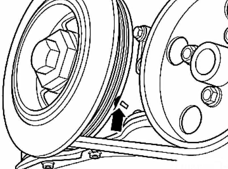
Give the crankshaft via a fixing bolt vibration damper in direction of rotation of the engine to the level of TDC cyl. 1 (Fig. 2.58). Remove ribbed belt. Remove the cylinder head cover and intake manifold.
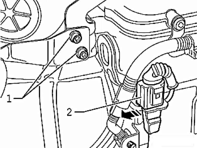
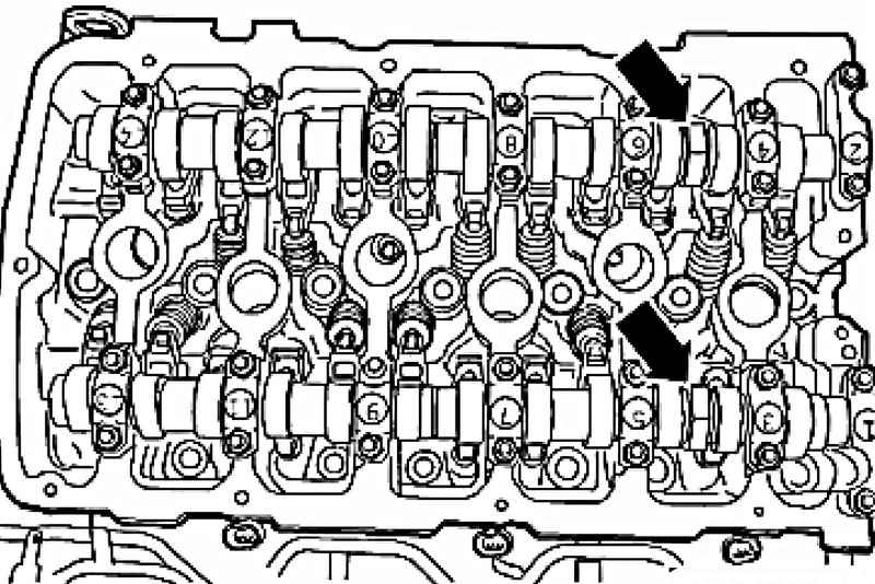
Remove the connecting wire 1 on the bracket support the intake manifold, and free plug knock sensor 1 G61 2 from its holder (Fig. 2.59). Then rasklipsuyte harness of mounting on the cylinder head.
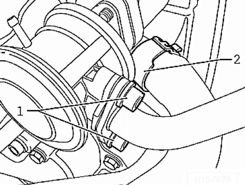
| Fig. 2.60. Pressure port combination valve and a water hose
|
Unscrew the discharge nozzle from the combination valve 1, and then disconnect the water hose 2 by a combined valve of the cylinder head (Fig. 2.60). Remove the exhaust manifold from the cylinder head. Remove the plugs from the valve of 1 system of variable valve timing and valve N205 1 of variable valve timing exhaust valves N318.
NOTE Before disconnecting the plug mark belonging to detail. |
Remove fixing collars harness from the bracket. Remove the thermostat housing and the cooling system installed on the engine.
Remove the side cover.
NOTE Side cover is "hidden bolt." Access to it is provided only after the removal of the thermostat housing. |
Unscrew all the mounting screws, gently pry the side cover down. Remove the mounting bolts of phase shifters.
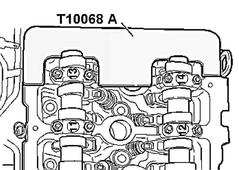
NOTE When loosening and tightening the camshaft phase shifters must be held only with the spanner 32 (Fig. 2.62). Ruler camshaft T10068 A should not be embedded in the groove. |
Remove the coupling permutations camshaft with roller chain timing from the intake shaft. Then remove the exhaust camshaft phaser.
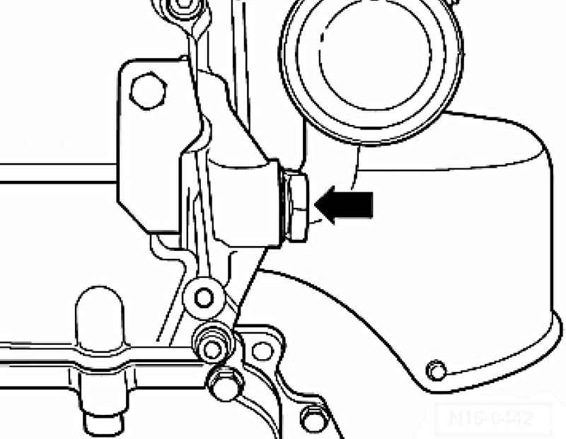
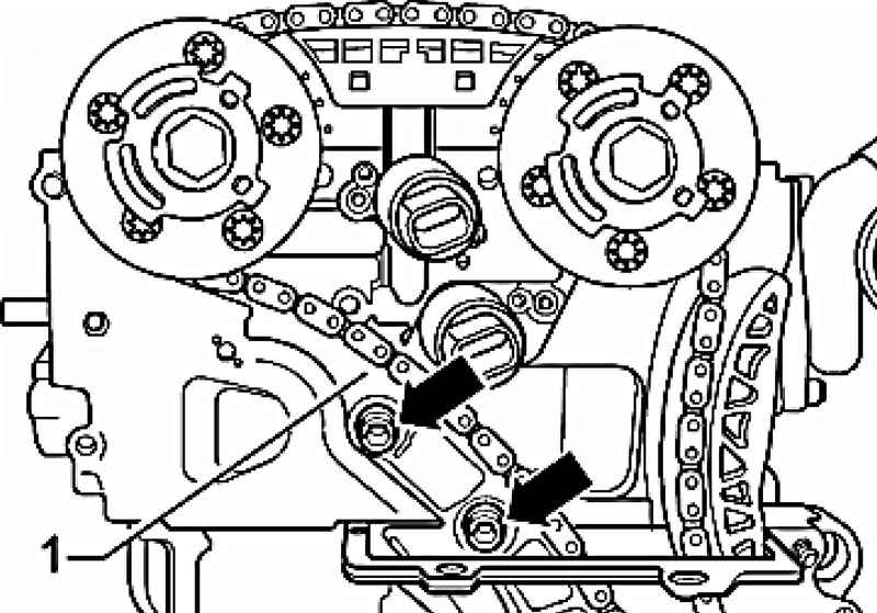
Turn off fixing bolts and remove the pacifier 1 bar (Fig. 2.63). Put the timing chain to the side, putting her side.
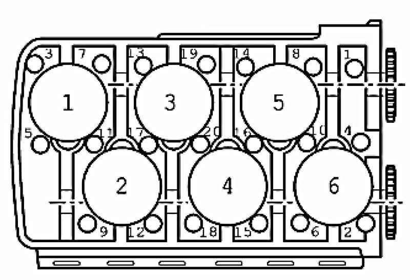
| Fig. 2.64. Order of easing of the cylinder head cover bolts
|
Loosen the cylinder head cover bolts in the sequence from outside to inside and unscrew them (Fig. 2.64).
NOTE For screws with heads Polydrive use key 3452. |
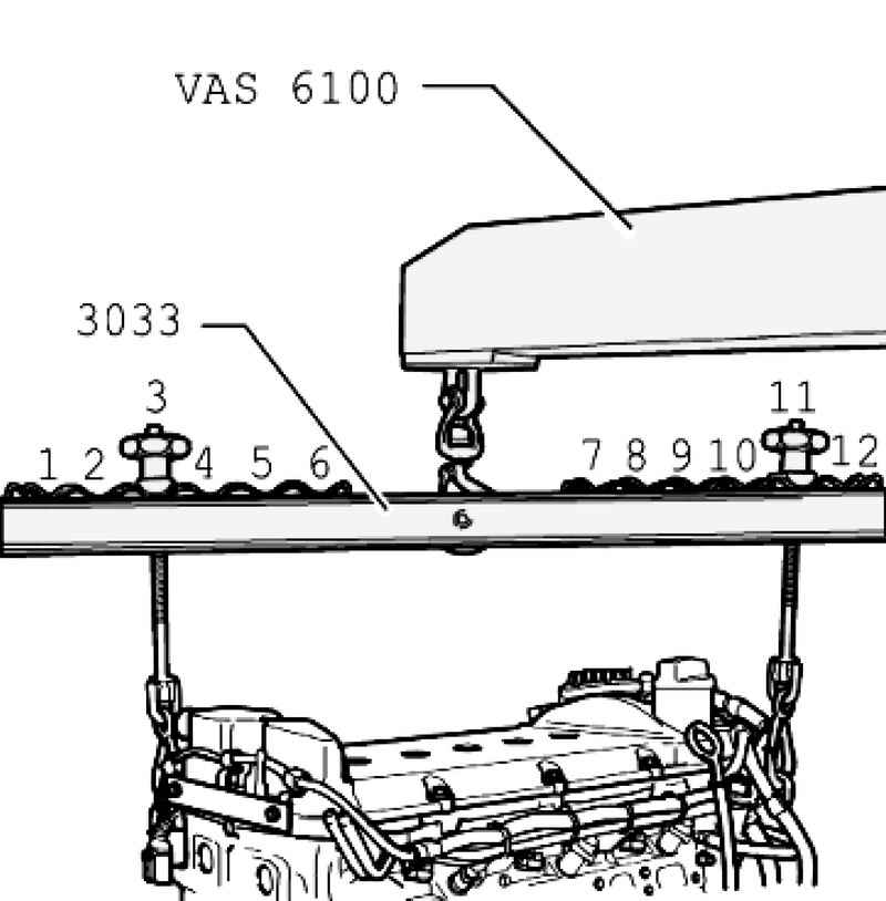
Hang the hanging device for 3033, as shown in Figure 2.65, and carefully lift the cylinder head by a crane VAS 6100 or VAG 1202 A. Side vibration damper: 3 position. Flywheel side: 11 position.
NOTE Marked 1 to 12 positions for hanging fixtures 3033 point in the direction of the flywheel (Fig. 2.65). Spindles are regulated if appropriate length. |
Carefully remove the cylinder head. Put into the cylinders a clean cloth to between the piston and the cylinder bore no dirt and the remains of emery. Check that the cooling liquid is also no dirt and the remains of emery. Carefully clean the sealing surfaces of cylinder head and cylinder block. Thus there should be no longer scratches and burrs (using grit sandpaper it should be less than "100"). Clean all threaded holes for the cylinder head cover bolts.
Setting Carefully remove remaining emery and sandpaper and rags of the cylinders. If the piston of 1st cylinder is not in TDC turn the crankshaft with the mounting bolt vibration damper in direction of rotation of the engine to the level of TDC cyl. 1. In this case, an assistant must move the hands of the timing chain synchronously in the same direction.
NOTE A new cylinder head gasket must be removed from the packaging until immediately before installation. Handle the new gasket very carefully. It will lead to further damage to the leak. |
Install the new cylinder head gasket. Marking (part number) has to be readable.
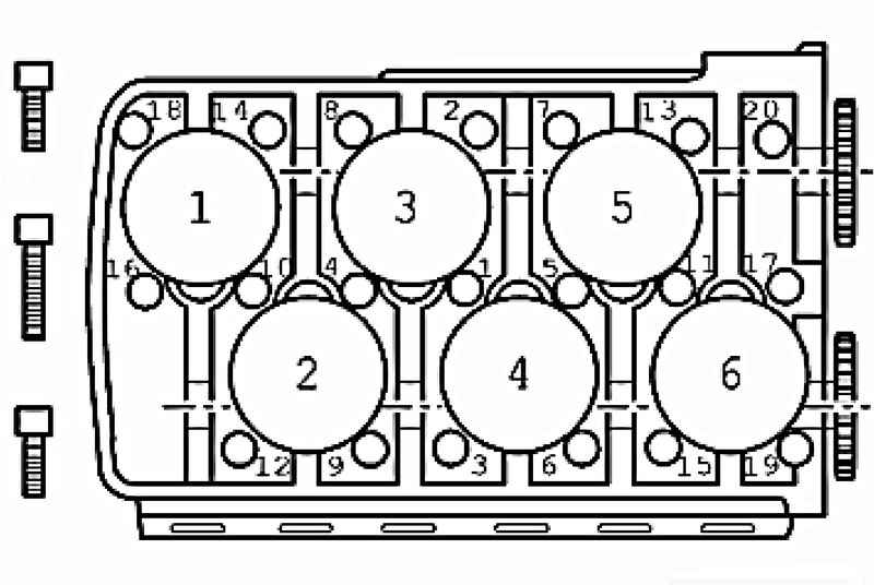
Check-fitting sleeves inserted in the holes 12 and 20 and the cylinder head gasket is fixed (Fig. 2.66). Turn the camshafts in cylinder head to TDC cylinder 1.
Ruler camshaft T10068 A should be included in both grooves (Fig. 2.67). Prepare cylinder head gasket to be installed. Install the cylinder head to the engine block, insert new cylinder head bolts and tighten them by hand. Tighten the cylinder head bolts in the shown in Figure 2.66 sequence from inside to outside.
NOTE Long cylinder head bolts are inserted into the middle hole in the cylinder head. |
Tighten all screws with a preliminary torque of 30 Nm. Then tighten all the bolts to a torque of 50 Nm. Then tighten all the bolts 1/4 turn (90 ?°), the usual key. Finally, tighten all bolts again a 1/4 turn (90 ?°). Further installation and assembly is performed in reverse sequence to removal.
NOTE Check inserted into the end cap O-ring of the oil channel. |
Install the cylinder head cover and intake manifold. Dotyazhka bolts of the cylinder head after a repair is not necessary.
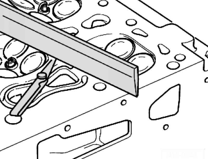
| Fig. 2.68. Checking cylinder head for warpage
|
Check the curvature of the contact surface of the cylinder head (Fig. 2.68). The maximum permissible bending: 0.05 mm.
|